Multi-chemistry plating system

a plating system and multi-chemistry technology, applied in the field of electrochemical plating system, can solve the problems of limited throughput of conventional plating system, difficulty in filling void-free interconnect feature via conventional metallization techniques,

Inactive Publication Date: 2007-05-29
APPLIED MATERIALS INC
View PDF126 Cites 42 Cited by
  • Summary
  • Abstract
  • Description
  • Claims
  • Application Information

AI Technical Summary

Problems solved by technology

However, as the interconnect sizes decrease and aspect ratios increase, void-free interconnect feature fill via conventional metallization techniques becomes increasingly difficult.
However, the throughput of conventional plating systems may be limited by the availability of the annealing chamber, as an annealing process for a semiconductor substrate after plating may take several minutes.
Further, once the annealing process is completed, the annealed substrate generally takes several minutes to cool down to a temperature that allows for transfer of the substrate to another processing chamber or device.

Method used


Image

  • Multi-chemistry plating system
  • Multi-chemistry plating system
  • Multi-chemistry plating system

Examples


Embodiment Construction

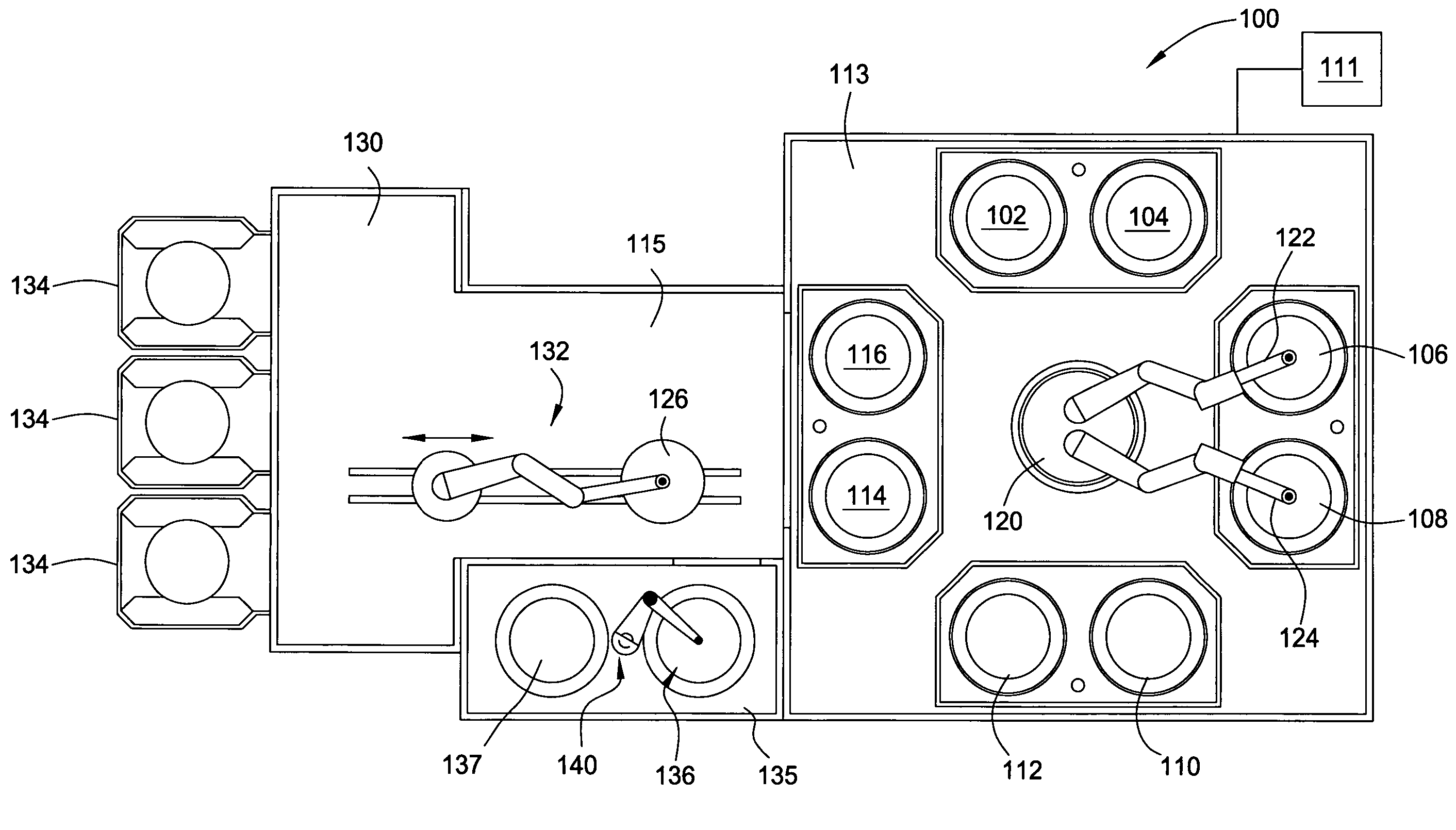
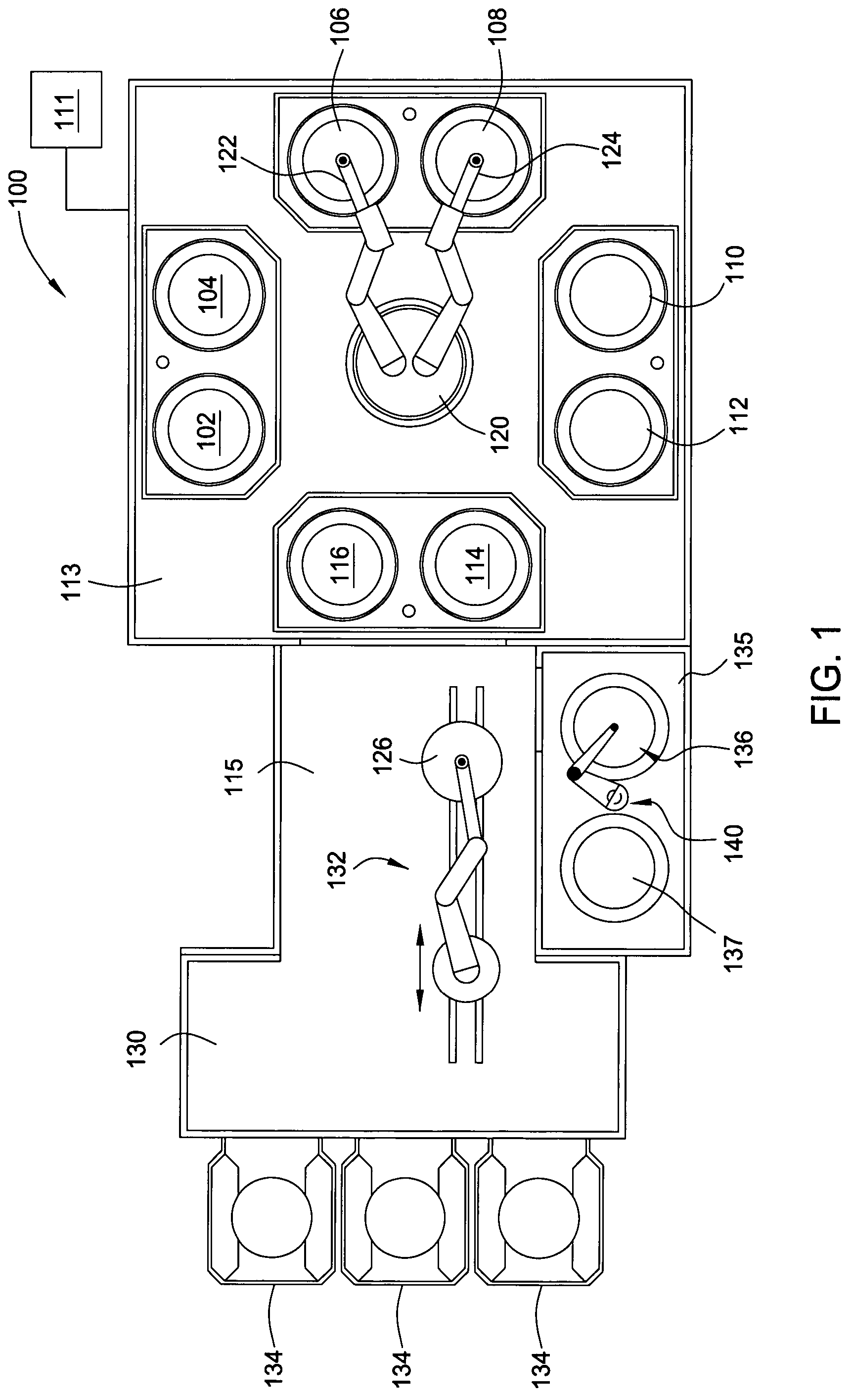
[0055]Embodiments of the invention generally provide a multi-chemistry electrochemical plating system configured to plate conductive materials onto semiconductor substrates. The plating system generally includes a substrate loading area in communication with a substrate processing platform. The loading area is generally configured to receive substrate containing cassettes and transfer substrates received from the cassettes to the processing platform for processing. The loading area generally includes a robot configured to transfer substrates to and from the cassettes and to the processing platform or a substrate annealing chamber positioned in communication with the loading area, processing platform, or a link tunnel positioned between the loading station and the processing platform. The processing platform generally includes at least one substrate transfer robot and a plurality of substrate processing cells, i.e., ECP cells, bevel clean cells, spin rinse dry cells, substrate cleani...


PUM

PropertyMeasurementUnit
tilt angleaaaaaaaaaa
temperatureaaaaaaaaaa

Abstract

Embodiments of the invention generally provide an electrochemical plating system. The plating system includes a substrate loading station positioned in communication with a mainframe processing platform, at least one substrate plating cell positioned on the mainframe, at least one substrate bevel cleaning cell positioned on the mainframe, and a stacked substrate annealing station positioned in communication with at least one of the mainframe and the loading station, each chamber in the stacked substrate annealing station having a heating plate, a cooling plate, and a substrate transfer robot therein.

Description

CROSS-REFERENCE TO RELATED APPLICATIONS[0001]This application is a continuation-in-part of co-pending U.S. patent application Ser. No. 10 / 438,624, filed May 14, 2003, which claims benefit of U.S. Provisional Patent Application Ser. No. 60 / 435,121, filed Dec. 19, 2002. This application is also a continuation-in-part of co-pending U.S. patent application Ser. No. 10 / 268,284, filed Oct. 9, 2002, which claims benefit of U.S. Provisional Patent Application Ser. No. 60 / 398,345, filed Jul. 24, 2002. This application also claims priority under § 119 to the following U.S. provisional applications:[0002]1) U.S. Provisional Patent Application Ser. No. 60 / 398,345, filed Jul. 24, 2002;[0003]2) U.S. Provisional Patent Application Ser. No. 60 / 435,121, filed Dec. 19, 2002;[0004]3) U.S. Provisional Patent Application Ser. No. 60 / 448,575, filed Feb. 18, 2003;[0005]4) U.S. Provisional Patent Application Ser. No. 60 / 463,956, filed Apr. 18, 2003;[0006]5) U.S. Provisional Patent Application Ser. No. 60 / 4...

Claims


Application Information

Patent Timeline
Patent Type & Authority Patents(United States)
IPC IPC(8): C25B9/12B08B3/02A23D7/00A23D7/005A23D7/01A23J7/00C25D7/12C25D17/00C25D21/00C25D21/08H01L21/00H01L21/68H01L21/683H01L21/687
CPCA23D7/00A23D7/005A23D7/01A23J7/00B08B3/02C25D21/08H01L21/67028H01L21/67034H01L21/67051H01L21/67109H01L21/6715H01L21/6719H01L21/67196H01L21/6723H01L21/68H01L21/68707C25D7/123C25D17/001C25D17/002C25D17/02C25D21/02H01L21/6838
Inventor YANG, MICHAEL X.XI, MINGELLWANGER, RUSSELL C.BRITCHER, ERIC B.DONOSO, BERNARDOPANG, LILY L.SHERMAN, SVETLANAHO, HENRYNGUYEN, ANH N.LERNER, ALEXANDER N.D'AMBRA, ALLEN L.SHANMUGASUNDRAM, ARULKUMARISHIKAWA, TETSUYARABINOVICH, YEVGENIYLUBOMIRSKY, DMITRYMOK, YEUK-FAI EDWINNGUYEN, SON T.
Owner APPLIED MATERIALS INC
Why Eureka
Try Eureka