Detection article having fluid control film

a technology of fluid control film and detection article, which is applied in the field of detection articles, can solve the problems of high manufacturing cost and difficult field testing, and achieve the effect of convenient detection and efficient and rapid handling of fluid samples

Inactive Publication Date: 2007-05-29
3M INNOVATIVE PROPERTIES CO
View PDF116 Cites 178 Cited by
  • Summary
  • Abstract
  • Description
  • Claims
  • Application Information

AI Technical Summary

Benefits of technology

[0013]The methods of the present invention include using the detection articles for glucose monitoring, enzyme-based testing, bacterial identification, antibody probe capture, characterization of biological macromolecules, DNA microarrays, sterilization assurance and numerous other biological assays. The methods of the present invention also include making the detection articles by continuous roll-to-roll processes. This enables the incorporation of high aspect ratio microreplicated channels with substructures such as nested channels to enhance flow dynamics and variable aspect ratios to control fluid flow timing or optical path-lengths. In addition, continuous processes provide for the patterning of organic or inorganic thin films to control surface energy and chemical absorption, the patterning of sample purification elements, assay reagent elements, microptical and flex circuit elements.
[0014]The present invention provides many benefits and advantages over prior art fluid sample testing devices, including precise control of fluid flow within the detection article, thus allowing for rapid fluid acquisition and distribution, as well as three dimensional flow control. The fluid streams within the article may be split and then re-associated if desired, and then re-split in a different manner, as needed, thus allowing for novel multiplexed tests. In addition, multiple layer articles may be provided with apertures fluidly connecting layers together.
[0015]Additionally, use of an open microstructure surface allows for easy placement of surface agents into desired regions to modify the fluid or to facilitate detection. Highly multi-plexed, miniaturized detection articles may be prepared by placing different detection elements into adjacent channels of the article, thereby facilitating detection of different results in each channel or detection of different levels or concentrations of the same result. Using an impermeable material to create the microstructure allows for the potential of an open dip stick without a protective cover, wherein the fluid sample may be held in the channels via surface tension, which can be a very strong retaining force. On the other hand, use of a semi-permeable material to create the microstructure would allow for controlled fluid diffusion to be employed. Optionally, a cap or cover layer may be provided, which may serve as a protective layer, may increase the wicking ability of the acquisition zone and / or may facilitate detection.
[0016]The fluid transport nature of the microstructured fluid control film layers used to form the detection articles of the present invention allows for the easy introduction of fluid sample into the structure through capillary action, without the need for additional processes such as sample input by syringe or pipetting. This feature makes the detection article faster and easier to use, cheaper to manufacture and use, and generally more versatile. The present invention also provides an ability to further process the film layer, such as by laminating a cap layer onto the film layer, forming multiple layer articles, and / or forming other structures.
[0017]Additional benefits include the ability to facilitate detection by observation or viewing of the detection zone through the provision of open channels, windows or optically transparent cap layers. Optical transmission through a microstructured cap layer or a fluid control film layer may be improved through the canting of the angles of the channels provided in the microstructured surface, or by other means.

Problems solved by technology

However, because of the bulk of the automated equipment, these tests are often difficult to perform in the field.
Glass and silicon based chips pose several practical problems to reaching these objectives.
These problems relate to the high cost of manufacture, incompatibilities between discrete processes for microfabrication of the glass substrates and continuous processes for incorporating the assay reagents, and the difficulties associated with sealing a glass cover onto the reagent impregnated chip.

Method used


Image

  • Detection article having fluid control film
  • Detection article having fluid control film
  • Detection article having fluid control film

Examples


example 1

Bacterial Identification

Run 1a: Preparation of Embossed Films.

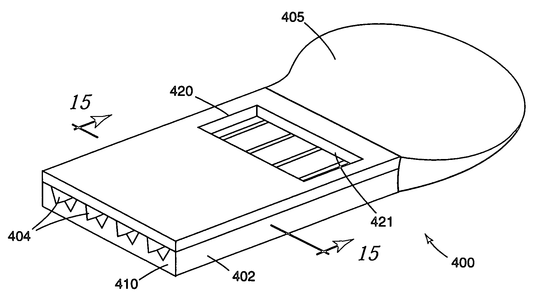
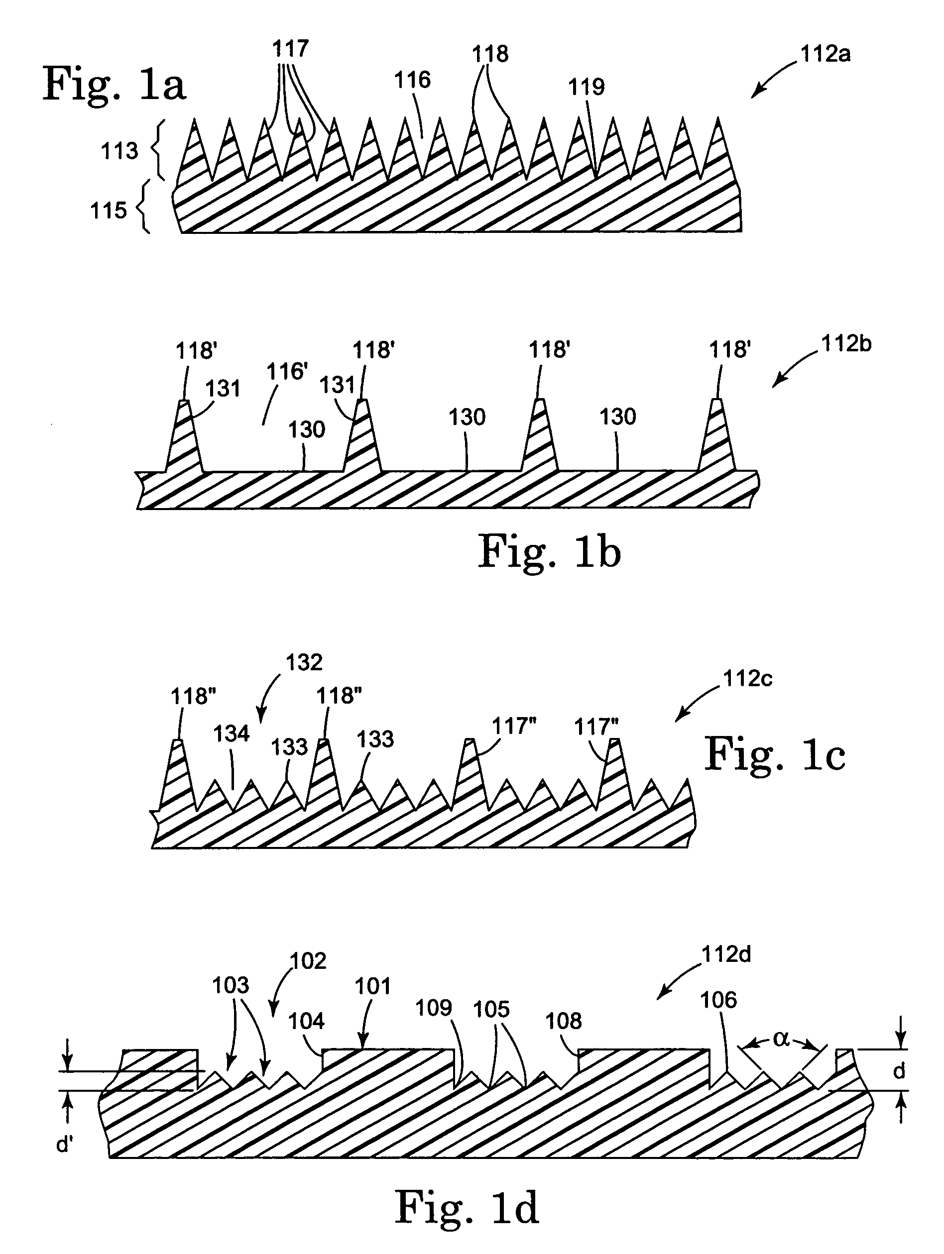
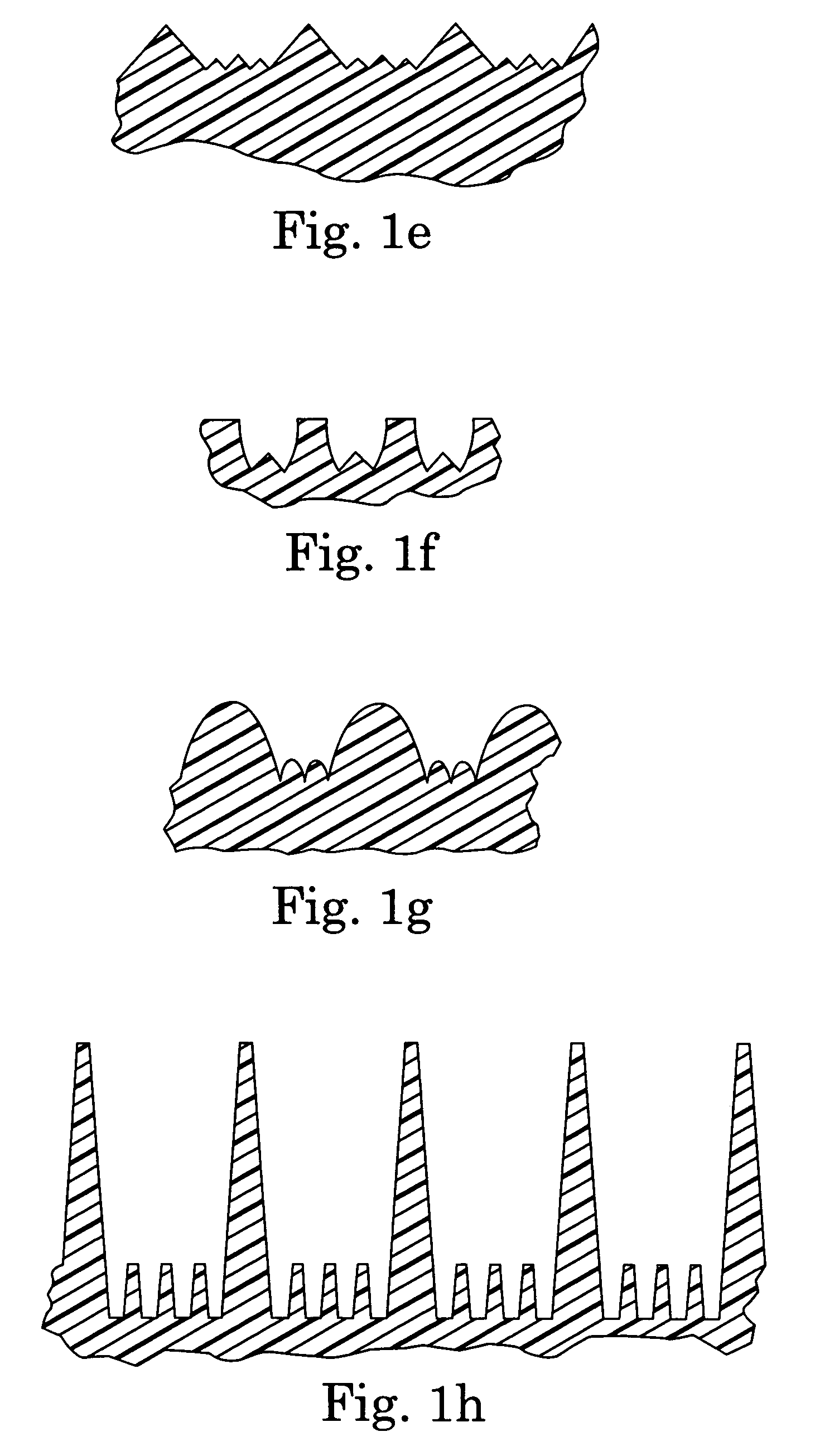
[0170]Films containing parallel channels were extrusion embossed onto a foam backing as described in U.S. patent application Ser. No. 08 / 905,481. The cross-section of each channel was in the shape of an inverted trapezoid having a base of approximately 0.75 mm and a height of approximately 1.0 mm. The sidewall angle was approximately 15 degrees. Each channel was separated by a “land area” of approximately 0.75 mm. The channels were sealed with a top film (ScotchPak #6, 3M Company) using a roll-to-roll laminator station heated to 149 degrees C. (300 degrees F.).

Run 1b: Substrate Profile Determination.

[0171]A commercial ID kit (BBL Enterotube II, Becton Dickenson Co.) containing the 12 tests outlined in Table 1 was used for comparison to the microchannel device. The hydrogel from each compartment of the ID kit was removed with a spatula and placed in a test tube. The hydrogel was melted by placing the tubes in a heated bloc...

example 2

Minimum Inhibitory Concentration (MIC) Test

Run 2a: Preparation of Microchannel Films.

[0175]Microchannel polyethylene films were heat embossed on a hydraulic press according to the procedure outlined in U.S. patent application Ser. No. 08 / 905,481. The channels used for this experiment had a rectangular cross-section of approximately 0.087 mm (0.022 inches) deep by approximately 1.96 mm (0.077 inches) wide. The channels were covered with ScotchPak #33 (3M Company) using an iron heated to 149 degrees C. (300 degrees F.), forming a series of capillary channels.

Run 2b: MIC Test Using Microchannels.

[0176]A dilution series of tetracycline was prepared in VRB media (7.0 g Bacto peptone, 3.0 g yeast extract, 1.5 g bile salts per liter) containing the fluorescent indicator methylumbelliferyl glucuronide (MUG, 0.5 mg / ml). The following tetracycline concentrations were prepared: 40, 4, 0.4, 0.04, and 0.004 micrograms / ml. Approximately 1 ml of each solution was placed in a test tube. A suspensio...

example 3

Gel Arrays Formed from Sheets of Microchannel Film

Run 3a: Preparation of Microchannel Film

[0177]Microchannel film was extrusion embossed according to the procedure of Johnston (U.S. Pat. No. 5,514,120). For the examples cited below two embossing tools were used. Tool 1 produced microchannel film with a “V channel” cross-sectional profile. The microchannels had a triangular cross-section with a base of approximately 0.3 mm and a height of approximately 0.35 mm. Tool 2 produced microchannels with a square cross-section approximately 0.2 mm by 0.2 mm. In addition, the microchannels from tool 2 produced a set of 4 smaller “nested” channels (˜50×50 microns) at the base of each microchannel.

Rune 3b: Preparation of Cubic Array Containing Isolated, Open-Ended Gel Zones

[0178]This run serves to demonstrate a “blank” array containing isolated, open-ended gels where each gel element is the same. To build an oligonucleotide array from such a device would require the use of a reactive gel and opt...


PUM

PropertyMeasurementUnit
contact angleaaaaaaaaaa
included angleaaaaaaaaaa

Abstract

The present invention provides a detection article including at least one fluid control film layer having at least one microstructured major surface with a plurality of microchannels therein. The microchannels are configured for uninterrupted fluid flow of a fluid sample throughout the article. The film layer includes an acquisition zone for drawing the fluid sample into the plurality of microchannels at least by spontaneous fluid transport. The film layer also includes a detection zone having at least one detection element that facilitates detection of a characteristic of the fluid sample within at least one microchannel of the detection zone.

Description

[0001]This application claims priority to U.S. provisional application Ser. No. 60 / 142,585, filed on Jul. 7, 1999 and entitled Detection Article Having Fluid Control Film.FIELD OF THE INVENTION[0002]This invention relates to articles that have the capability to control or transport fluids, especially biological fluids. In particular, this invention relates to articles that have the capability for acquisition and transport of such fluids for subsequent detection purposes.BACKGROUND OF THE INVENTION[0003]Biological assays that require sample partitioning are traditionally performed in test-tubes or microwell arrays and require manual intervention at several stages to enable the sampling, purification, reagent addition, and detection steps required to make the assay selective and specific. Ongoing developments in this field have focused on the ability to rapidly process fluid samples in order to increase efficiency and cost effectiveness. In some cases, automated sample handling equipm...

Claims


Application Information

Patent Timeline
Patent Type & Authority Patents(United States)
IPC IPC(8): C12M1/14G01N1/10
CPCB01L3/5023B01L3/502707B01L3/502746B01L2300/0825B01L2300/0887B01L2300/161B01L2400/0406
Inventor JOHNSTON, RAYMOND P.FLEMING, PATRICK R.HALVERSON, KURT J.BENTSEN, JAMES G.KREJCAREK, GARY E.SANO, KOICHI
Owner 3M INNOVATIVE PROPERTIES CO
Why Eureka
Try Eureka