Bluff body energy converter

a technology of energy converter and bluff body, which is applied in the direction of electric generator control, fluid coupling, coupling, etc., can solve the problems of membrane deformation and vibration

Active Publication Date: 2007-05-29
OCEAN POWER TECHNOLOGIES
View PDF8 Cites 79 Cited by
  • Summary
  • Abstract
  • Description
  • Claims
  • Application Information

AI Technical Summary

Problems solved by technology

This unsteady traveling pressure wave causes the membrane to deform and vibrate.

Method used


Image

  • Bluff body energy converter
  • Bluff body energy converter
  • Bluff body energy converter

Examples


Embodiment Construction

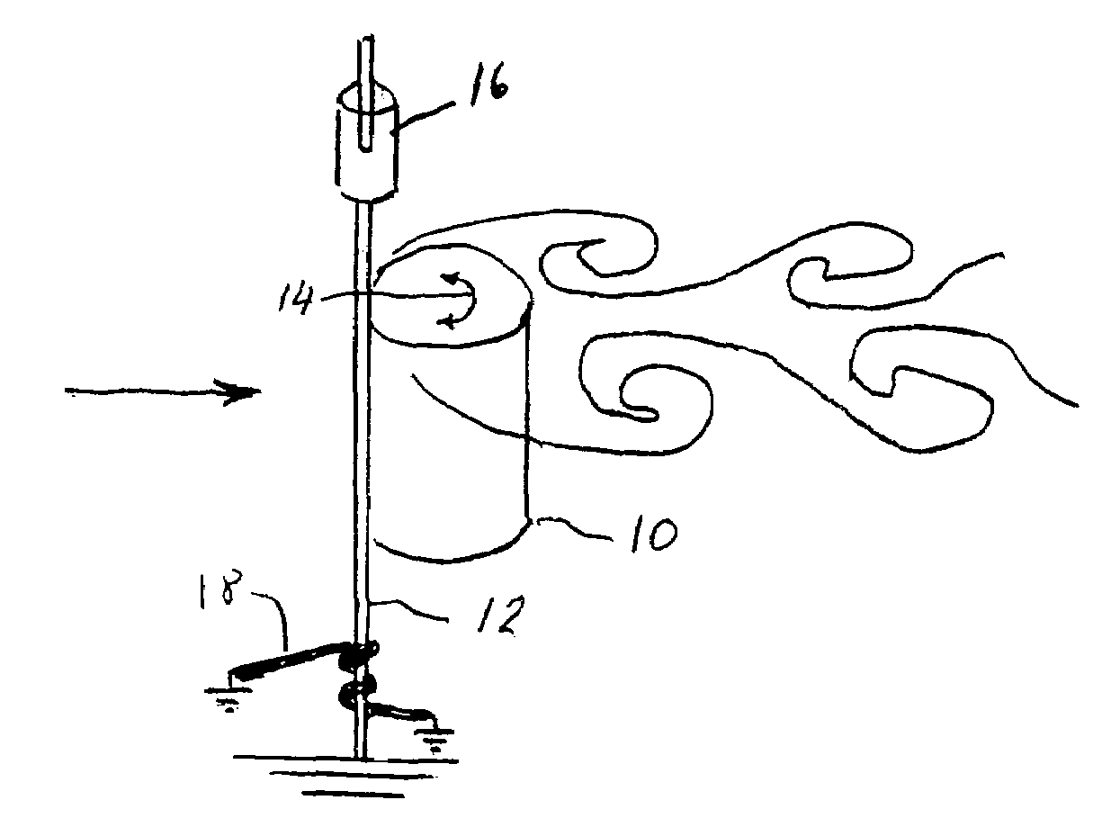
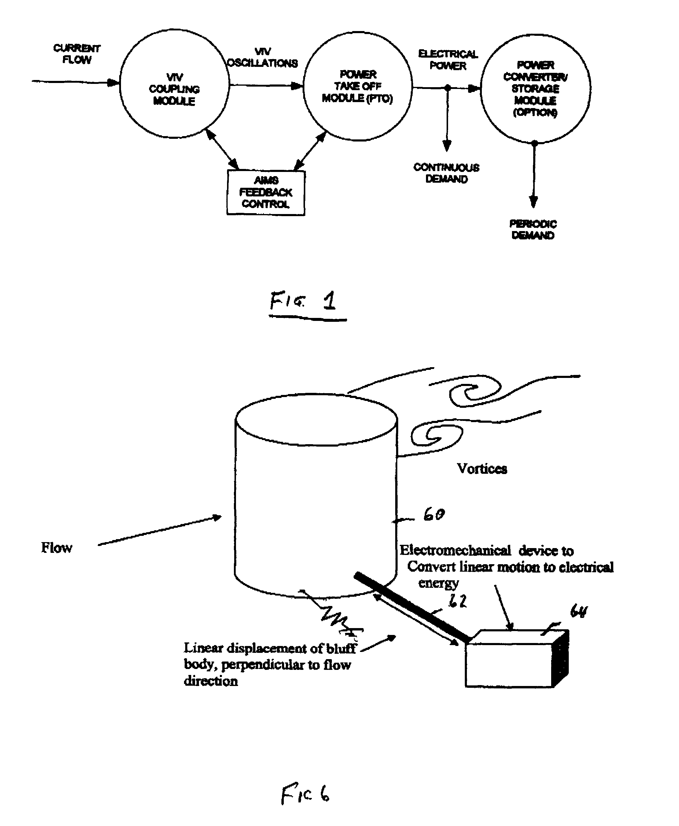
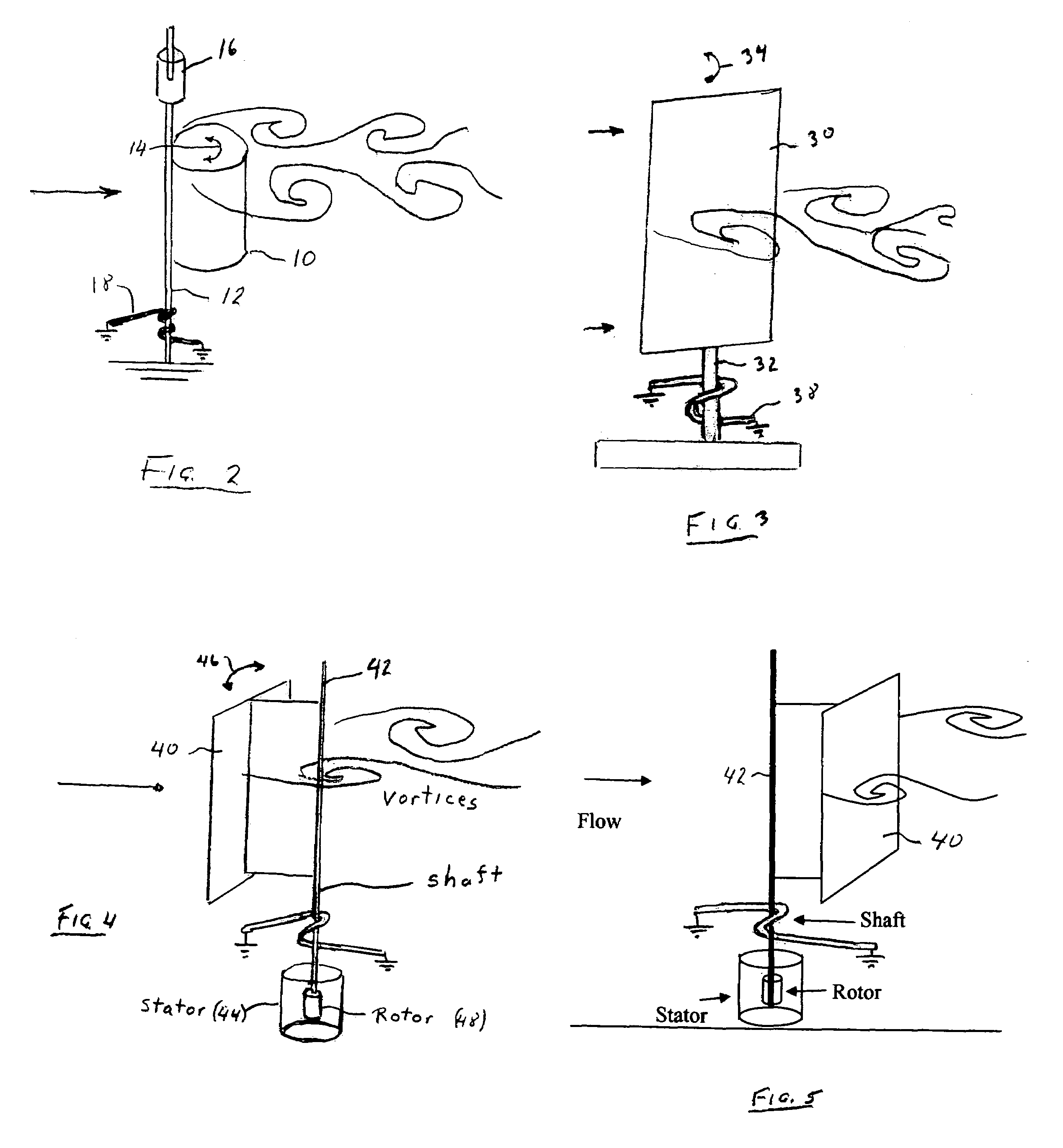
[0010]FIG. 1 is a systems diagram illustrating the basic concepts of the invention. A bluff body is placed at 90 degrees to the oncoming fluid stream to disrupt the flow and generate (shed) vortices of alternating rotation from the edges of the body.

[0011]By a “bluff body” is meant an object having a non-streamlined shape that produces considerable resistance when immersed in a moving fluid. A region of separated flow occurs over a large portion of the surface of a bluff body, which results in a high pressure drag force and a large wake region. The flow often exhibits unsteadiness in the form of periodic vortex formation and shedding. Bluff bodies are widely encountered in many engineering applications and design problems, including bridges, stacks, power lines and the like. Numerous published studies of bluff bodies are available.

[0012]In accordance with this invention, a bluff body, mounted for oscillatory movements about its major axis, is disposed in a fluid stream perpendicular...


PUM


Abstract

A power generating system comprises a bluff (non-streamlined) body placed in a fluid stream at ninety degrees to the flow direction for creating a von Karman vortex street behind the body. In the process, feedback forces are generated that excite the bluff body into oscillation. The bluff body oscillatory movements are coupled to and energize a power generator. An impedance matching system is employed for electrically varying the natural frequency characteristics of the bluff body such that, over a relatively wide range of fluid flow velocities, the bluff body oscillates at a resonant frequency of the body for maximum energy transfer from the fluid stream to the bluff body.

Description

CROSS REFERENCES TO RELATED APPLICATIONS[0001]This application claims priority from provisional patent application Ser. No. 60 / 536,397 titled current Flow Energy Converter filed Jan. 14, 1004, the teachings of which are incorporated herein by reference.BACKGROUND OF THE INVENTION[0002]This invention relates to the conversion of energy from fluid streams, for example, winds and ocean currents, and particularly to the use of bluff bodies disposed in such streams for capturing energy by the shedding of vortices from the bodies.[0003]The use of bluff bodies for interacting with fluid streams for capturing energy there from is known. In U.S. Pat. No. 6,424,079, “Energy Harvesting Eel”, for example, a bluff body in the form of a flat plate is placed at 90 degrees to the oncoming stream of water resulting in the generation of vortices at the plate edges. The vortices travel downstream of the plate to interact with a membrane of a piezoelectric power generator. The oscillating series of vor...

Claims


Application Information

Patent Timeline
Patent Type & Authority Patents(United States)
IPC IPC(8): H02P9/04
CPCF03D5/00F03D5/06F05B2210/16F05B2260/96Y02E10/70
Inventor ALLEN, JAMES J.
Owner OCEAN POWER TECHNOLOGIES
Why Eureka
Try Eureka