Methods and apparatus for displaying decorative ornament curtains

a technology for decorative ornaments and curtains, applied in curtain suspension devices, door/window protective devices, light support devices, etc., can solve the problems of ornament curtain design, ornament curtain one-to-one orientation is often compromised, and crystal surface is typically interrupted by many openings and gaps, so as to minimize the appearance of gaps and voids, enhance the effect of visual effect, and improve the design of ornament curtain

Active Publication Date: 2007-06-05
W SCHONBEK LLC
View PDF31 Cites 25 Cited by
  • Summary
  • Abstract
  • Description
  • Claims
  • Application Information

AI Technical Summary

Benefits of technology

[0015]Aspects of the invention allow for the construction of dense ornamental crystal curtains, for example, extremely dense ornamental crystal curtains, compared to the prior art. In addition, aspects of the invention provide for the introduction of blended color patterns in the crystal curtains, for example, complex blended color patters. Aspects of the invention provide the designer with numerous exciting aesthetic design possibilities.
[0023]These and other aspects of the present invention provide improvements over the prior art, specifically, improvements in ornament curtain design that minimizes the appearance of gaps and voids between ornaments. In addition, aspects of the present invention provide the ornamental fixture designer with a vehicle for providing enhanced visual effect that heretofore was unavailable. These advantages and improvements will become more readily apparent upon review of the myriad aspects of the present invention illustrated in and described with respect to the enclosed drawings.

Problems solved by technology

Historically, spherical faceted beads have had some limited use in the construction of chandeliers.
As a result, when using wire lops, the orientation of ornaments one-to-another was often compromised.
For example, the resulting crystal surface was typically interrupted by many openings and gaps due to the imprecision of the positioning of the ornaments, for example, the octagonal ornaments.
Even with the use and broad acceptance of the Schonbek connector, the resulting crystal curtains that used these connectors often lacked “density,” that is, often lacked a uniform continuous ornament display.
Among other things, this lack of density is primarily due to the gaps or discontinuities that could appear between adjacent ornaments.
Among other things, these gaps 16 reduce the visually density of the display and introduce unsightly views into the interior of the chandelier.
Though an improvement in the art, the arrangements shown in FIGS. 2A and 2B are still far from ideal.
However, arrangement 40 is also undesirable because it is characterized by especially unsightly gaps 45 at the top of the alternating chains 44, 48.
However, these designs have generally been unsatisfactory for a number of reasons.
For example, given their spherical shape, facetted beads are not a cost effective means of covering an ornamental surface.
Furthermore, satisfactory methods for precisely positioning of such beads did not exist in the art.
Though arrangement 50 produces a dense crystal curtain, the disadvantage of arrangement 50 is that square crystals are not preferred; specifically, the faceting pattern of square crystals inherently reduces the prismatic effect of the appearance of the fixture.
However, clearly, these, and other, examples of prior art crystal mounting arrangements are characterized by undesirable gaps between ornaments.
These gaps not only interrupt the desired uniform continuous display preferred in lighting fixtures, but these gaps may also undesirably expose internal components of the fixture, for example, internal structural components, that may be unsightly or simply interfere with the desired presentation intended by the designer of the fixture.

Method used


Image

  • Methods and apparatus for displaying decorative ornament curtains
  • Methods and apparatus for displaying decorative ornament curtains
  • Methods and apparatus for displaying decorative ornament curtains

Examples


Embodiment Construction

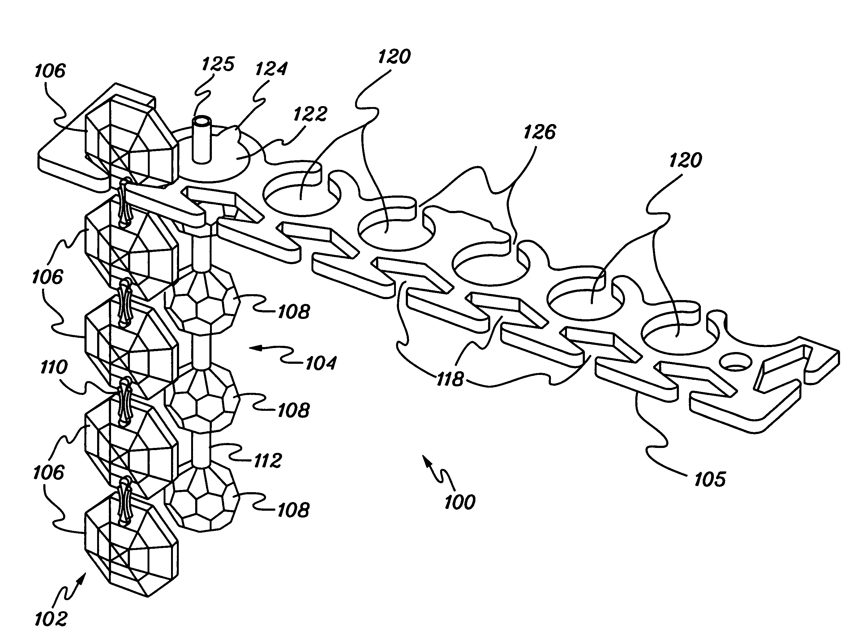
[0048]Aspects of the invention are illustrated in FIGS. 6A through 6D. FIG. 6A is perspective view of an ornament arrangement or fixture 100 according to one aspect of the present invention. FIG. 6B is a partial front elevation view of the ornament arrangement 100 shown in FIG. 6A. According to aspects of the invention, arrangement 100 includes a plurality of ornament crystal chains 102 and 104 suspended from a gallery plate 105. In one aspect of the invention, chain 104 may comprise an ornamental element, such as, an individual crystal or rod. Arrangement 100 shown in FIG. 6A illustrates only a single ornament chain 102 and a single ornament chain 104 to facilitate illustration of aspects of the invention. However, typically, aspects of the invention include a plurality of ornament chains 102 and a plurality of ornament chains 104. FIG. 6C is a partial plan view of gallery plate 105 from which ornament chains 102 and 104 may be suspended. FIG. 6D is a top view of arrangement 100 sh...


PUM


Abstract

When displaying decorative ornaments in vertical chains, that is, as ornament curtains, for example, in light fixtures, gaps or voids between the ornaments can detract from the overall visual appeal. Methods and apparatus of the present invention minimize the gaps and voids in an ornament display to provide a denser display of ornaments than the existing art. According to aspects of the invention, the denser ornament display is achieved by mounting ornament chains in gallery rings that suspend the ornament chains in staggered relationship either in multiple planes or within the same plane whereby the ornaments fill the gaps and voids in the visual field of the viewer. The invention also includes improved gallery rings and ornament chains that are adapted to be mounted to the improved gallery rings. Aspects of the invention may be used in many types of ornamental light fixtures, such as, chandeliers.

Description

TECHNICAL FIELD[0001]The present invention concerns methods and apparatus for supporting decorative ornaments, for example, ornamental crystals. Specifically, the present invention concerns methods and apparatus for supporting decorative ornaments in decorative ornamental curtains while minimizing undesirable gaps and voids between ornaments, for example, for use in light fixtures, such as chandeliers.BACKGROUND INFORMATION[0002]In the construction of ornamental lighting fixtures, such as chandeliers, it is common to incorporate vertical “curtains” of decorative ornaments. These curtains are typically are made from “chains” of ornaments, for example, chains of suspended octagonal crystals. The most widely used and cost effective crystal element used in the construction of crystal chandeliers is the 14-millimeter (mm) octagon. For example, the 14-mm octagon is the preferred ornament used for candle-to-candle swag chains in traditional chandeliers, vertical curtain chains for contempo...

Claims


Application Information

Patent Timeline
Patent Type & Authority Patents(United States)
IPC IPC(8): A47H23/05
CPCF21S8/065F21V5/06F21S4/008F21V15/01F21V21/005F21S4/28
Inventor SCHONBEK, ANDREW J.LUSSIER, STEVENSCHUYLER, ANDREW
Owner W SCHONBEK LLC
Why Eureka
Try Eureka