Device for coupling implement to agricultural tractor

a technology for agricultural implements and coupling hooks, which is applied in the direction of towing devices, adjusting devices, agriculture tools and machines, etc., can solve the problems of complicated operation of coupling release, high cost, and difficulty in removing coupling hooks, so as to achieve simple operation from the driver's seat and low cost.

Inactive Publication Date: 2007-06-05
KABUSHIKI KAISHA DELICA
View PDF19 Cites 10 Cited by
  • Summary
  • Abstract
  • Description
  • Claims
  • Application Information

AI Technical Summary

Benefits of technology

[0009]An object of the present invention is to provide a device for coupling an agricultural implement to an agricultural tractor, the device being composed of a small number of parts and being capable of being operated easily from the driver's seat when the coupling is released.
[0013]According to the present invention, the control lever is provided with a slit extending obliquely upward. Therefore, when the coupling is released, the operator has only to slide the control lever obliquely upward, toward the driver's seat, and then to turn the control lever slightly forward. The operation from the driver's seat is thus very simple, so the hook is useful. In addition, since the stopper can be operated only with the control lever, the hook only requires a few parts, and the cost is consequently low.

Problems solved by technology

Therefore, there are a large number of parts and the cost can be high.
Thus, the operation from the driver's seat, which is located diagonally in front of the coupling hook, becomes complicated.
Therefore, operation for releasing the coupling is complicated.

Method used


Image

  • Device for coupling implement to agricultural tractor
  • Device for coupling implement to agricultural tractor
  • Device for coupling implement to agricultural tractor

Examples


Embodiment Construction

[0020]The preferred embodiments of the present invention will now be described with reference to FIGS. 1 to 6.

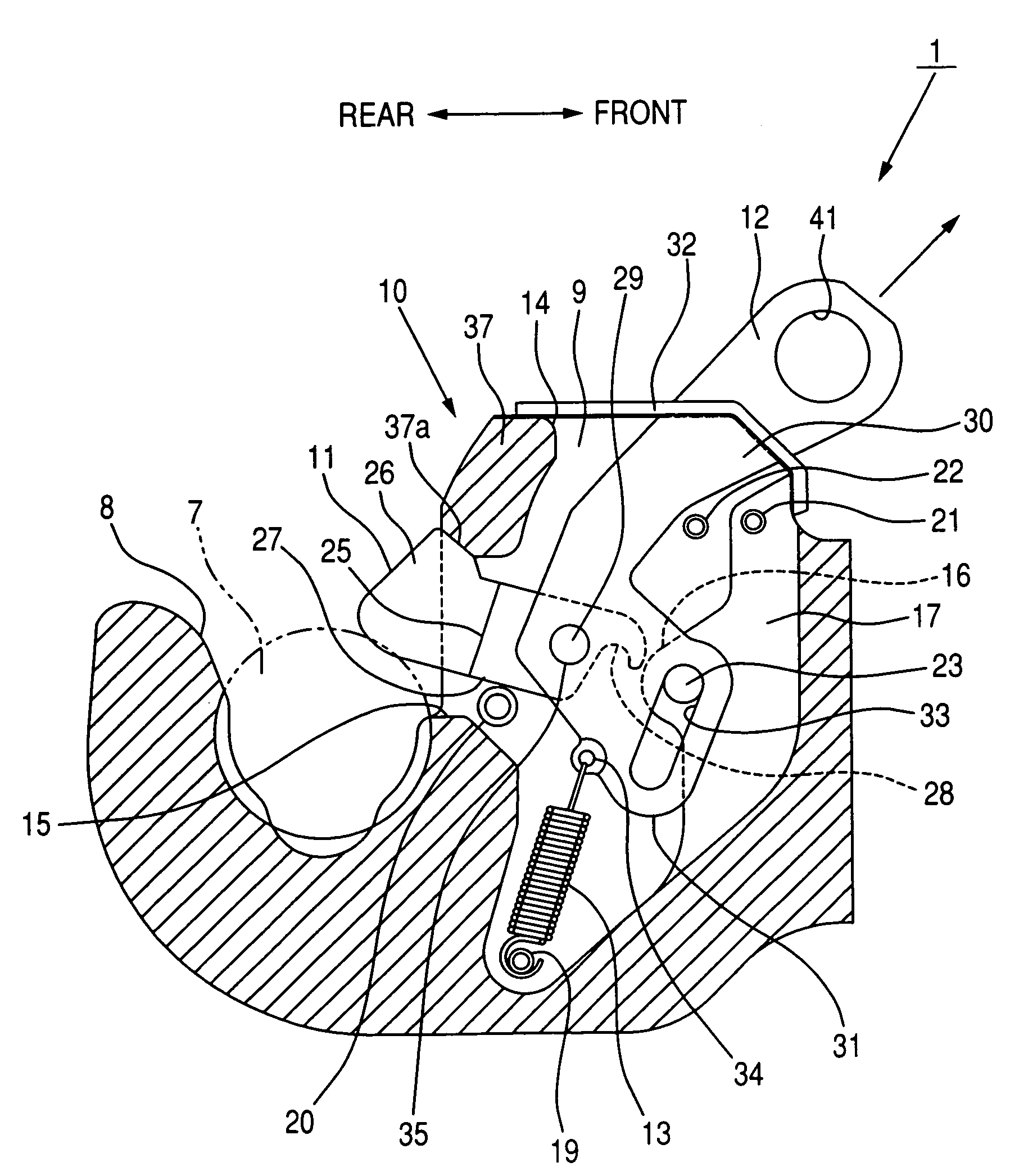
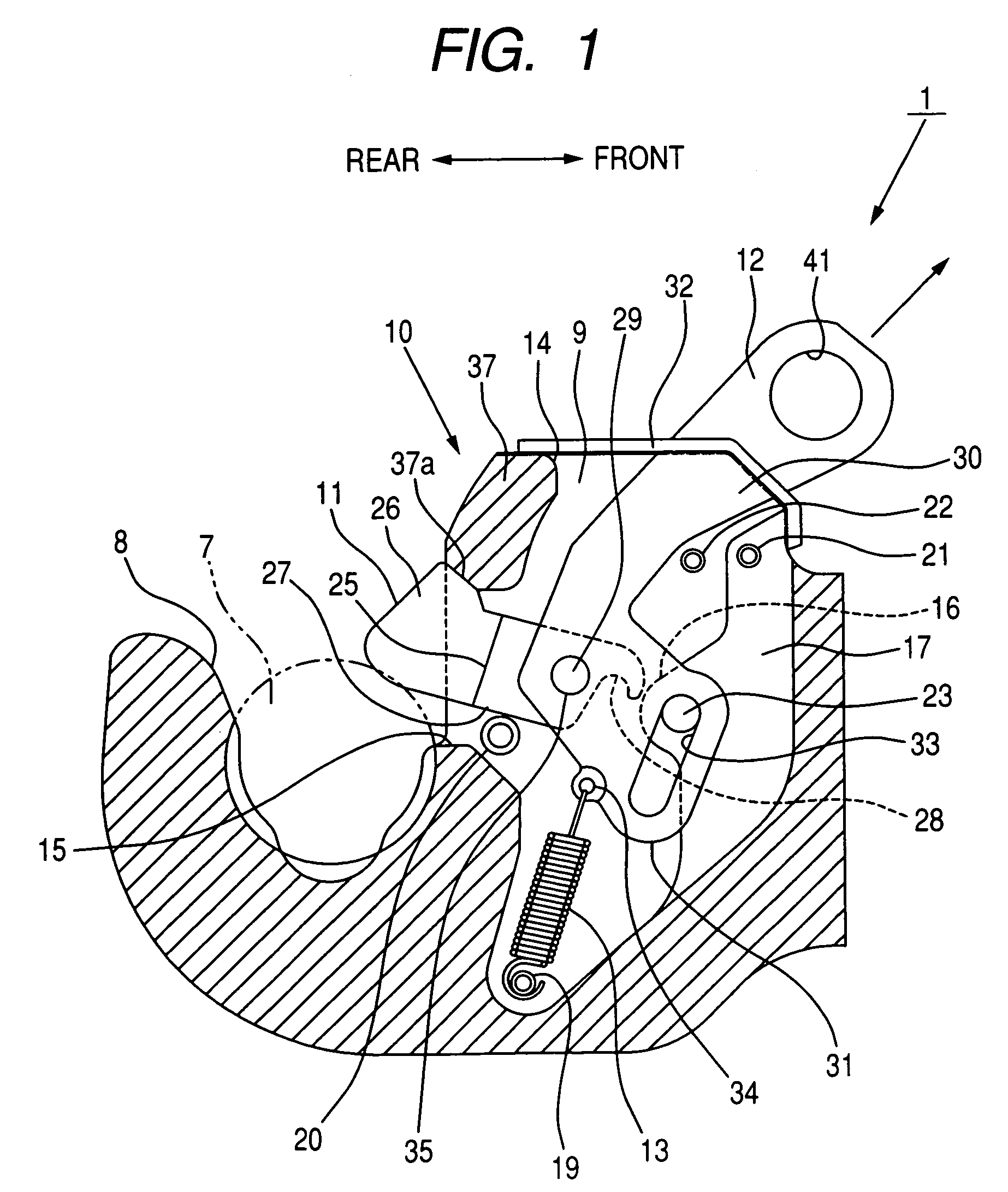
[0021]FIG. 6 shows an agricultural tractor 2 having an upper link 4 and a lower link 5 at its rear end. A coupling device 1 to which an agricultural implement 3 is coupled is attached to the rear end of the lower link 5. A coupling ball 7 provided at the front end of the agricultural implement 3 is locked in the coupling device 1, whereby the agricultural tractor 2 and the agricultural implement 3 are coupled together.

[0022]As shown in FIGS. 1 to 4, the coupling device 1 for coupling the agricultural implement 3 to the agricultural tractor 2 according to the present invention mainly includes a hook main body 10 having a hook portion 8 for accommodating the coupling ball 7 and a cavity 9 provided by the side of the hook portion 8; a stopper 11 disposed in the cavity 9 and for locking the coupling ball 7; a control lever 12 coupled to the stopper 11 and for sliding the stopper...


PUM


Abstract

The invention relates to a device for a coupling an agricultural implement to an agricultural tractor, in which the operation to release the coupling between the agricultural implement and the agricultural tractor can be easily implemented.When the coupling of the agricultural tractor and the agricultural implement is released, first, a control lever of a coupling hook is slid upward against the urging force of a spring until a second guide pin reaches the lower end of a slit. Next, the control lever is turned forward around the second guide pin until a bent portion of the upper portion and the lower portion of the control lever comes into contact with a first guide pin. As a result, the rear end of a stopper is retracted into a cavity in the hook main body of the device through a second opening so as to slide to the coupling-ball-releasing position, and a groove of the stopper is hooked to a hooking pin so as to be fixed.

Description

BACKGROUND OF THE INVENTION[0001]1. Field of the Invention[0002]The present invention relates to a device for coupling an agricultural implement to an agricultural tractor.[0003]2. Description of the Related Art[0004]In general, a link is provided at the rear of an agricultural tractor. A device for coupling an agricultural implement (hereinafter referred to as “coupling device”) is attached at the rear end of the link. When an agricultural implement is coupled to an agricultural tractor, first, a coupling ball provided in the front portion of the implement is accommodated in a hook portion provided in the coupling device of the agricultural tractor. Next, the coupling ball is locked with a stopper of the coupling device so as not to be escaped from the hook portion of the coupling device. When the coupling is to be released, first, the operator pulls a control lever of the coupling device so as to slide the stopper to the coupling-ball-releasing position, and the stopper is held in...

Claims


Application Information

Patent Timeline
Patent Type & Authority Patents(United States)
IPC IPC(8): A01B51/00A01B59/00A01B59/043B60D1/04
CPCA01B59/006B60D1/04
Inventor YAMADA, SHOICHIYAMAMOTO, TAKAOOKUBO, SEIJI
Owner KABUSHIKI KAISHA DELICA
Why Eureka
Try Eureka