Shock absorbent packaging structure

a packaging structure and shock absorption technology, applied in the direction of packaging goods, transportation and packaging, tray containers, etc., can solve the problems of serious storage problems and the need for substantial thickness of foam structure for shock absorption, and achieve the effect of enhancing shock absorption ability and large loading area

Active Publication Date: 2007-06-05
AU OPTRONICS CORP
View PDF13 Cites 15 Cited by
  • Summary
  • Abstract
  • Description
  • Claims
  • Application Information

AI Technical Summary

Benefits of technology

[0007]Accordingly, an object of the invention is to provide a packaging structure with larger loading area to enhance shock absorbent ability.
[0009]The separators have one top side, one bottom side and two lateral sides inserted in the first and second grooves respectively. The bottom side of the separator abuts the connecting plate when the separator is sealed in the first and second grooves. The separator has a notch at the top side enabling easy removal of the glass substrate from the first and second grooves.
[0012]The long plate is folded such that the first, second, third, fourth, fifth, sixth, seventh, eighth, ninth, tenth and eleventh sections form respectively a first plate, the first bottom wall, the first outer wall, the first top wall, a second plate, the connecting plate, a third plate, the second top wall, the second outer wall, the second bottom wall and a fourth plate; the first section slots overlap the fifth section slots to form the first portion grooves, and the seven section slots overlaps the eleventh section slots to form the second portion grooves. The second plate is bonded to the first plate to form the first inner wall, and the fourth plate is bonded to the third plate to form the second inner wall, thereby providing stiffness and rigidity of the first and second portions.

Problems solved by technology

However, the foam structure must provide a considerable thickness for shock absorption.
This results in a large volume, creating a serious problem for storage.

Method used


Image

  • Shock absorbent packaging structure
  • Shock absorbent packaging structure
  • Shock absorbent packaging structure

Examples


Embodiment Construction

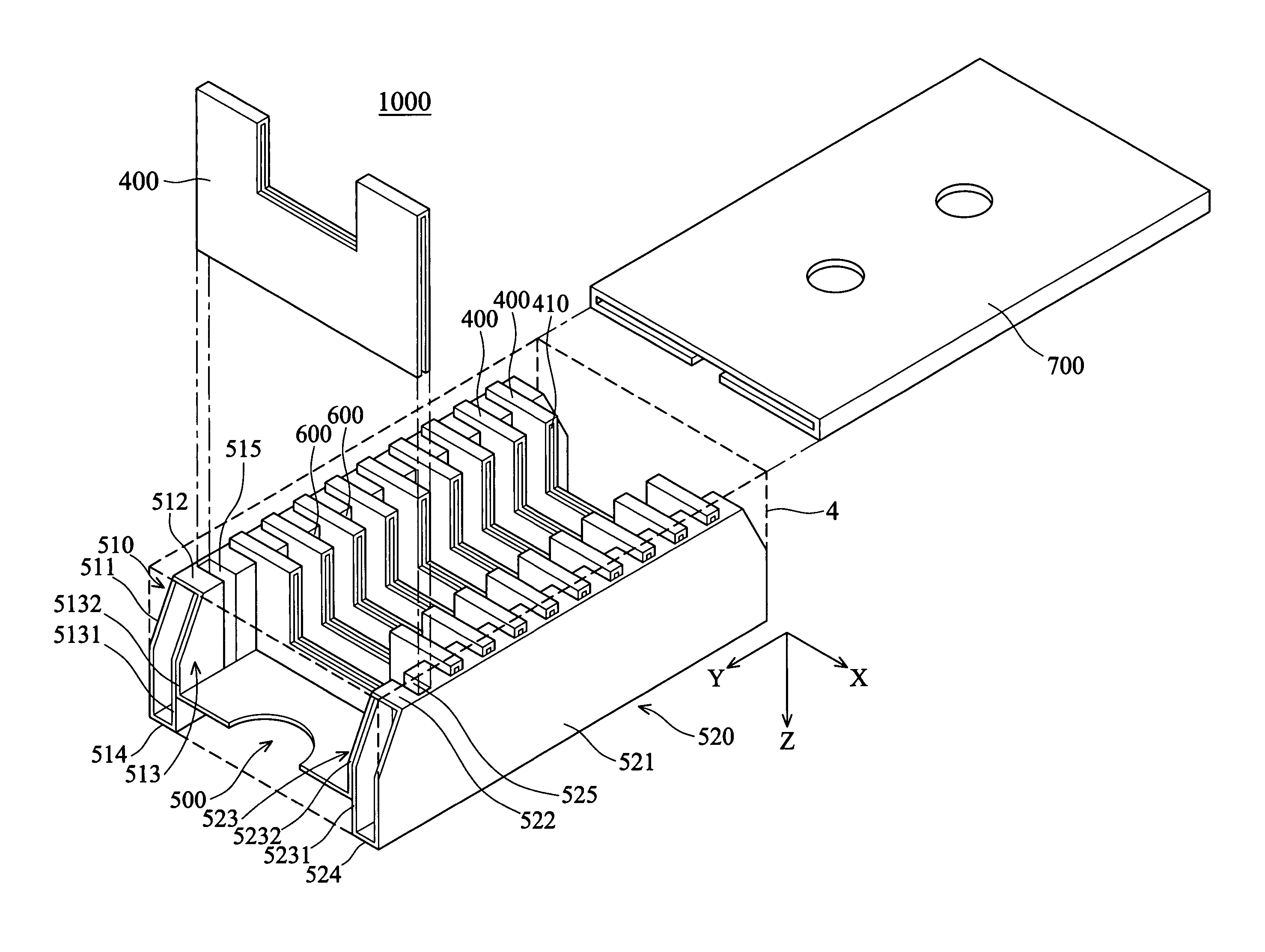
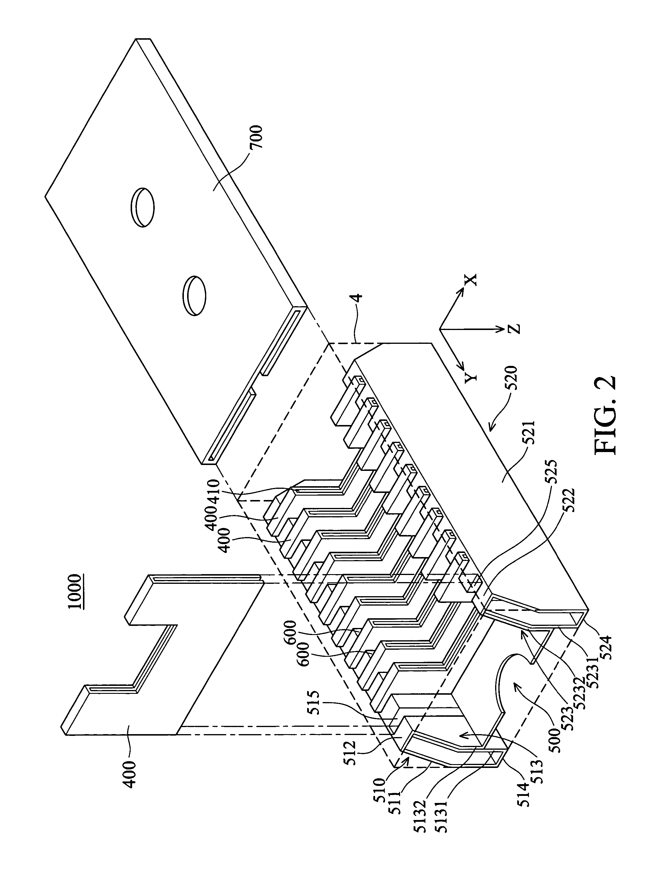
[0021]FIG. 2 is a perspective view of a packaging structure of the invention. The packaging structure 1000 of the invention comprises a main frame 500 and a plurality of separators 400. The main frame comprises a first portion 510, a second portion 520 and a connecting plate 530 connecting the first portion 510 and the second portion 520. The first portion 510 is substantially rectangular and includes an outer wall 511, a top wall 512, an inner wall 513 and a bottom wall 514. The second portion 520 is also substantially rectangular and symmetrical to the first portion 510 with respect to the connecting plate 530. Similarly, the second portion 520 includes an outer wall 521, a top wall 522, an inner wall 523 and a bottom wall 524. The connecting plate 530 connects the first portion inner wall 513 and the second portion inner wall 523.

[0022]A plurality of first grooves 515 is defined on the first portion inner wall 513 perpendicular to the first portion top wall 512. Similarly, a plur...


PUM


Abstract

A packaging structure for a container. The packaging structure includes a main frame including a first portion, a second portion and a connecting plate connecting the first and second portions, and a plurality of separators inserted in first and second grooves defined at the first and second portions respectively. The glass substrate is sealed in a loading slot formed by the separators.

Description

BACKGROUND OF THE INVENTION[0001]1. Field of the Invention[0002]The present invention relates to a shock absorbent packaging structure, and in particular to a packaging structure provided with a larger loading area for better shock absorption.[0003]2. Description of the Related Art[0004]A glass substrate for a liquid crystal panel, either unprocessed or substrate, must be transported in a special container to avoid damage caused by impact. Conventionally, a shock absorbent packaging structure of foam material is inserted in a container for the glass substrate. However, the foam structure must provide a considerable thickness for shock absorption. This results in a large volume, creating a serious problem for storage. Therefore, long paper plates have become preferred rather than the foam material.[0005]FIG. 1 shows a conventional shock absorbent packaging structure using paper plates. The packaging structure 10 in FIG. 1 comprises a main frame 20 and a carrying body 30 provided with...

Claims


Application Information

Patent Timeline
Patent Type & Authority Patents(United States)
IPC IPC(8): B65D85/48B65D85/30B65D5/49
CPCB65D5/48046B65D85/48
Inventor CHEN, CHIU-CHUNCHOU, BO-CHICHANG, WEN-YUAN
Owner AU OPTRONICS CORP
Why Eureka
Try Eureka