Suction device

a suction device and manual operation technology, applied in the direction of machine supports, building scaffolds, other domestic objects, etc., can solve the problems of damage to the surface to which the holder is attached, the inability of the holder to be easily moved to other sites, and the inability of the holder to be fixed with adhesives to facilitate the movement of the holder, etc., to achieve the effect of enhancing the operation efficiency of the suction devi

Active Publication Date: 2007-06-05
SONNENSCHEIN IND
View PDF21 Cites 84 Cited by
  • Summary
  • Abstract
  • Description
  • Claims
  • Application Information

AI Technical Summary

Benefits of technology

[0008]An objective of the present invention is to provide a suction device comprising a rotatable cap which, after rotation in a predetermined direction, causes deformation of a deformable suction cup to induce a suction force for attaching the suction device to a smooth fixed surface, and which, due to rotation in an opposite direction, releases the deformation of the cup and thus the suction force to allow removal of the suction device from the fixed surface, whereby operation efficiency of the suction device is enhanced.

Problems solved by technology

Using bolts to fix the mobile phone holder usually causes damage to the surface to which the holder is attached.
Further, the holder is not allowed to readily move to other sites.
Similarly, fixing the holder with adhesives does not allow the holder to be readily moved.
Such a mark is difficult to clean off.
A small cup usually leads to a small and insufficient suction force that cannot firmly and stably supports a mobile phone or other objects.
However, a large cup requires a large footprint on the fixed surface, which causes inconvenience in operating the suction cup.
In addition, the large cup often deteriorates overall surface aesthetics, due to occupation of large space.

Method used


Image

  • Suction device
  • Suction device
  • Suction device

Examples


Embodiment Construction

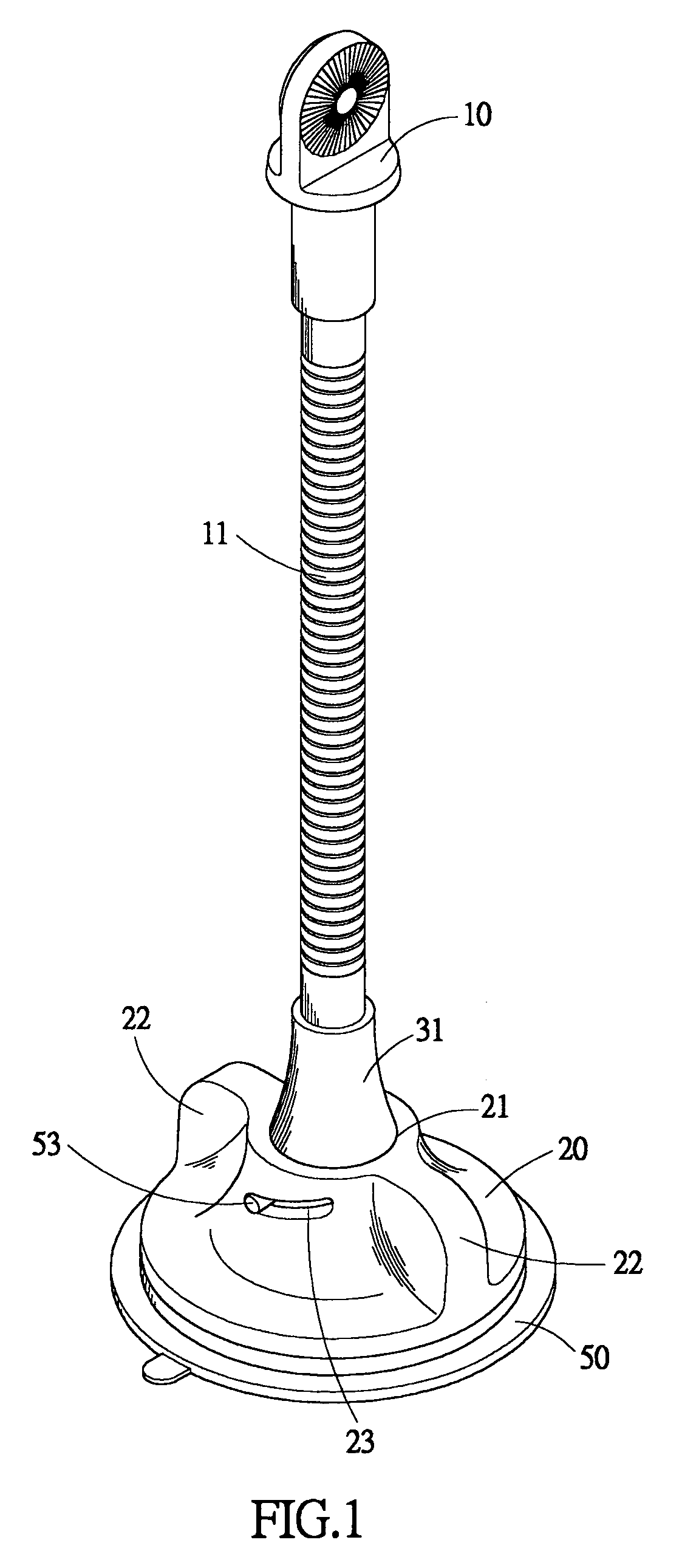
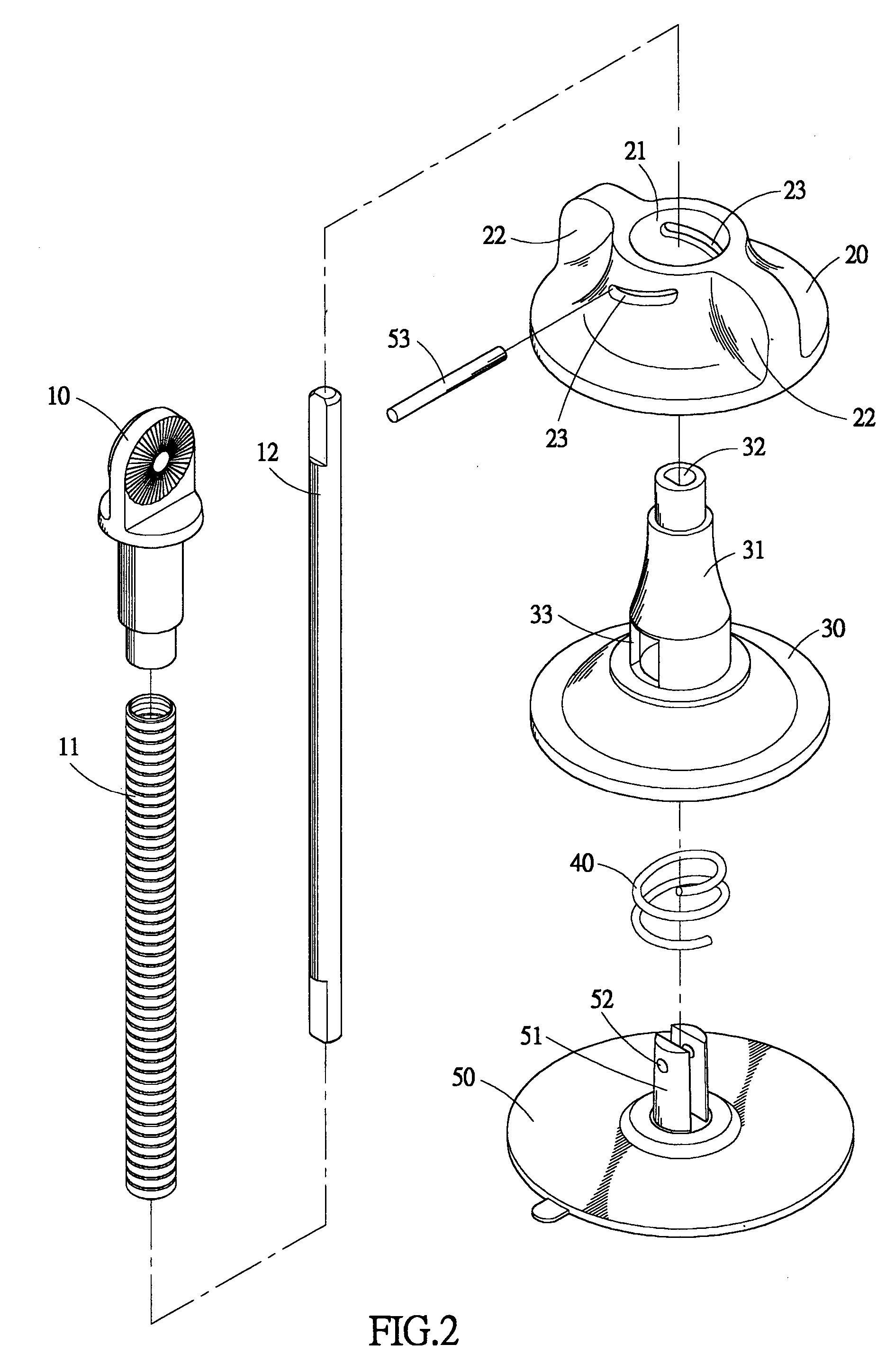
[0015]With reference to the drawings and in particular to FIGS. 1 and 2, which show, respectively, a perspective view and an exploded view of a suction device constructed in accordance with the present invention, comprises a deformable suction cup 50, a resilient member 40, an inner presser cap 30, an outer rotatable cap 20, and an article support member 10.

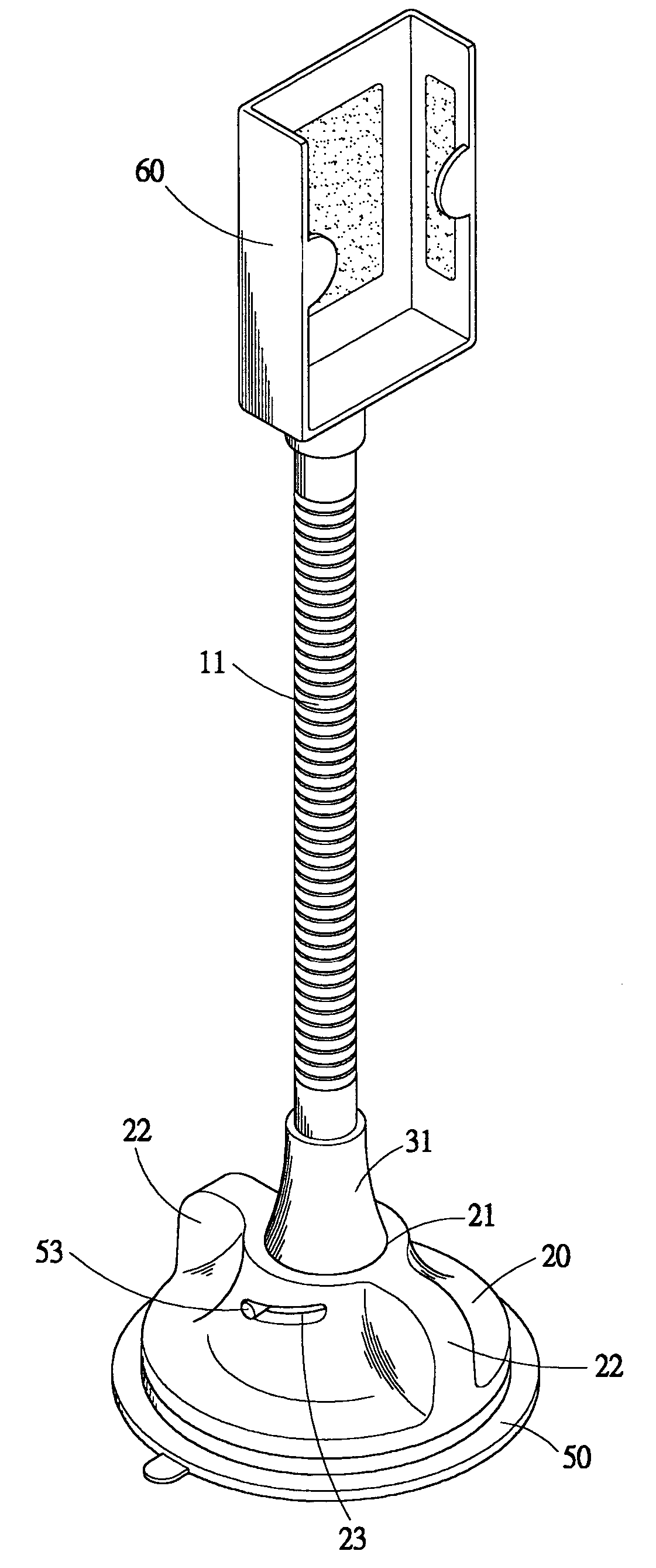
[0016]Also referring to FIG. 4, which shows a perspective view illustrating an application of the suction device of the present invention, the article support member 10 that is supported by a flexible tube 11 and a flexible bar 12 extending from the inner cap 30 rotatably supports an article receptacle 60 in which an article, such as a mobile phone and a PDA (not shown) can be received and retained.

[0017]As shown in FIG. 2, the flexible tube 11 and the flexible bar 12 that is received in and co-extends with the flexible tube 11 in a coaxial manner are mounted, at upper ends thereof, to a lower end of the article support member 10...


PUM


Abstract

A suction device includes a suction cup having a peg extending therefrom and a transverse shaft extending in opposite directions from the peg, an inner cap positioned on the suction cup and retaining a spring that applies a restoring force to the suction cup, and an outer cap positioned on the inner cap and defining inclined slots in which the opposite ends of the shaft are movably received, respectively. By rotating the outer cap with respect to the inner cap causes camming action between each inclined slot and the respective end of the shaft, which in turn imposes a driving force on the peg to deform the suction cup thereby inducing a suction force. An elongate flexible member has a first end coupled to the inner cap and an opposite second end rotatably supporting an article receptacle in which an article, such as mobile phone and a personal digital assistant can be received and retained.

Description

BACKGROUND OF THE INVENTION[0001]1. Field of the Invention[0002]The present invention generally relates to a manually-operated suction device, and in particular to a suction device that attaches / separates an article, such as a mobile phone and a personal digital assistant (PDA), to / from a smooth flat surface by rotating a rotatable cap to cause / release deformation of a suction cup, which induces a suction force between the cup and the surface due to pressure difference.[0003]2. The Related Art[0004]It is common to retain a mobile phone or a PDA on a designated sites, such as inside a car or on a office table, by a mobile phone holder, to allow a mobile phone user to take an incoming call or make an outgoing call without hand holding the phone, whereby the user is allowed to proceed with what is being done without interference caused by operating the phone.[0005]A conventional mobile phone holder employs fasteners, such as bolts, to fix the holder to the designated site. Using bolts ...

Claims


Application Information

Patent Timeline
Patent Type & Authority Patents(United States)
IPC IPC(8): A45D42/14F16B47/00
CPCB60R11/00F16B47/00F16M13/00F16M11/041F16M13/022F16M11/40B60R2011/0056B60R2011/0091F16M2200/08
Inventor LIN, CHRISTINA
Owner SONNENSCHEIN IND
Why Eureka
Try Eureka