Vehicle suspension system

a suspension system and vehicle technology, applied in the direction of shock absorbers, mechanical equipment, transportation and packaging, etc., can solve the problems of excessive force, achieve the effect of improving damper tuning, improving damper bushing durability, and improving ride to the vehicl

Inactive Publication Date: 2007-06-05
FIRESTONE IND PROD COMPANY
View PDF18 Cites 30 Cited by
  • Summary
  • Abstract
  • Description
  • Claims
  • Application Information

AI Technical Summary

Benefits of technology

[0011]A further advantage of the invention is to mount the restraining cylinder by a flexible member which allows the canister to move with the damper / air spring and accommodate larger coning angles of the damper piston rod.
[0012]A further feature of the invention is to form the restraining canister of a rigid rubber material containing radial reinforcement cords, thereby providing a rigid structure unaffected by the harsh environment which is experienced by the suspension system.
[0013]Another aspect of the invention is to provide a vehicle suspension system which by separating the attachment loads, provides improved damper tuning, ride isolation from the damper bushing, improved damper bushing durability, and provides an improved ride to the vehicle by reducing the vibration exerted on the chassis by the damper / air spring combination.

Problems solved by technology

Although such attachments perform satisfactory in many applications, it does exert an excessive force on a common attachment location which absorbs both the forces exerted on the air spring as well as the damper.

Method used


Image

  • Vehicle suspension system
  • Vehicle suspension system
  • Vehicle suspension system

Examples


Embodiment Construction

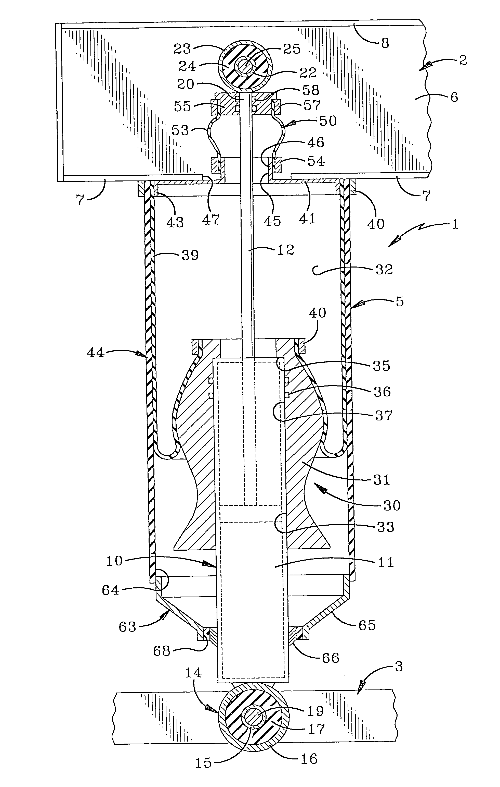
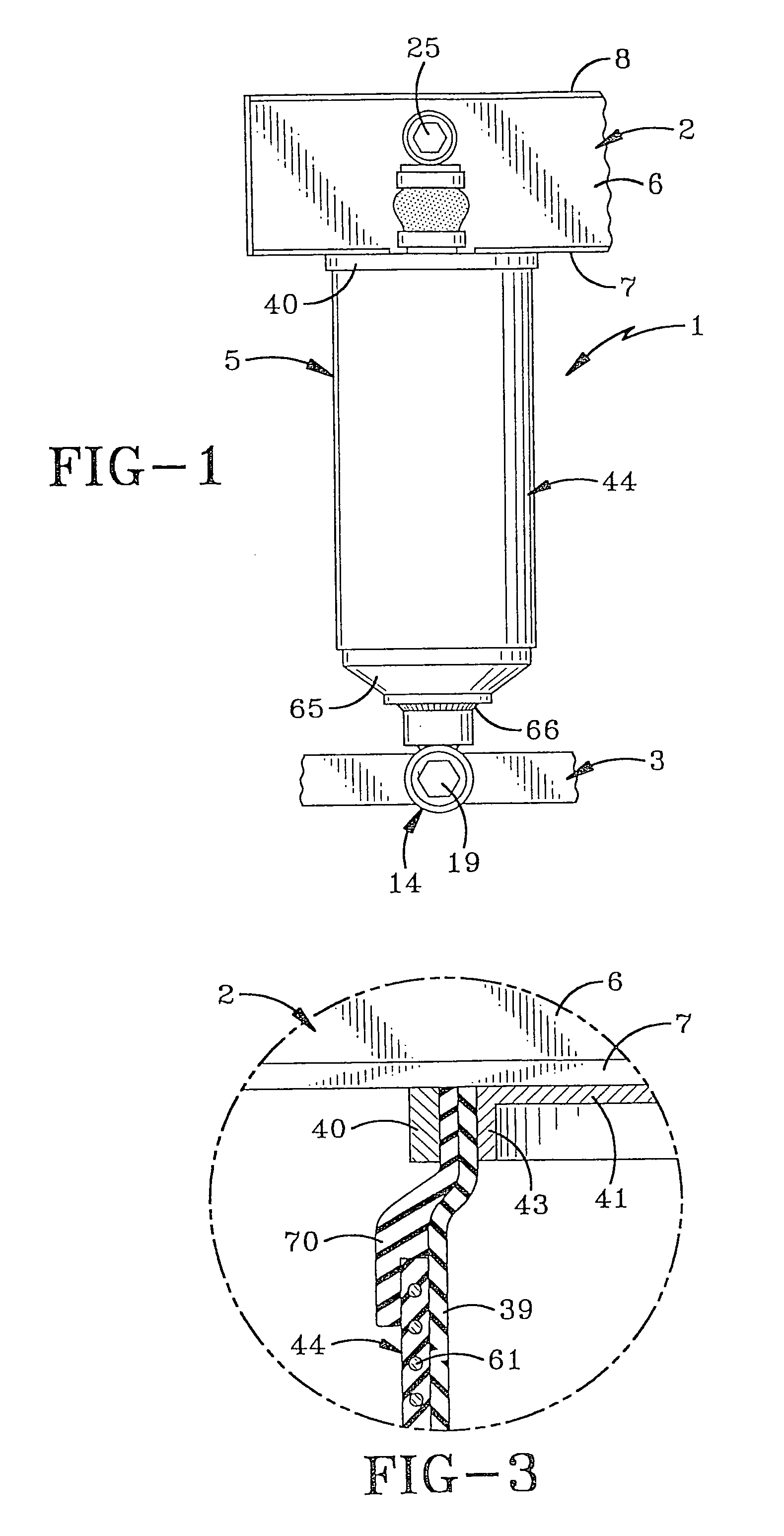
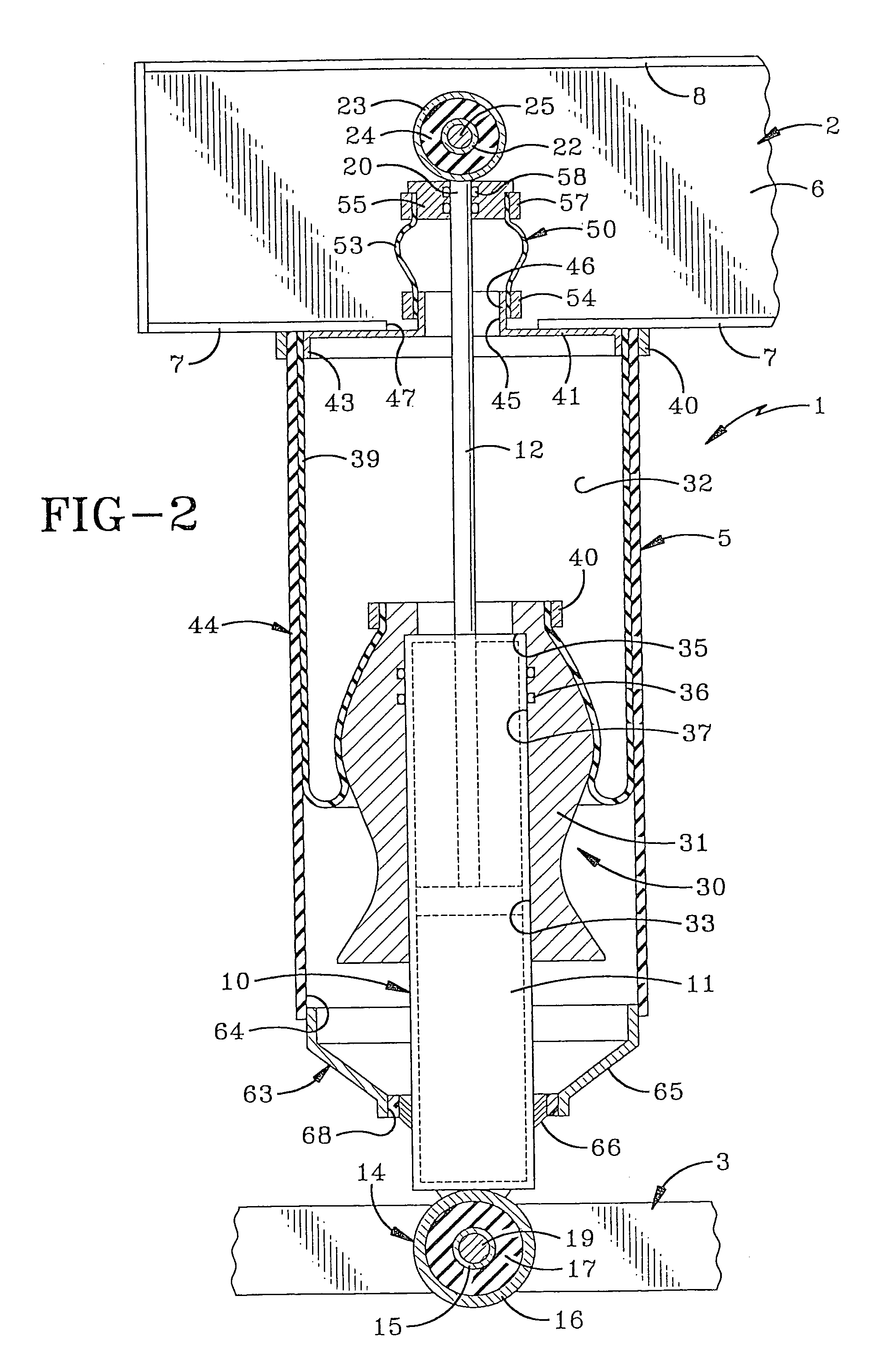
[0019]FIG. 1 is a side elevational view of the improved vehicle suspension system which is indicated generally at 1, which includes a pair of spaced vehicle components indicated generally at 2 and 3, having an air spring / damper combination 5 mounted therebetween. Vehicle components 2 and 3 can be various structural parts of a vehicle and in the preferred embodiment, component 2 is a channel shaped chassis frame member having a web wall 6 and a pair of spaced outwardly extending channel legs 7 and 8. Lower component 3 could be various components of the wheel assembly.

[0020]Air spring / damper combination 5 (FIG. 2) includes a damper indicated generally at 10, having a cylinder 11 containing a fluid such as oil, in which is reciprocally mounted a piston rod 12. The lower end of cylinder 11 is connected to vehicle component 3 by an elastomeric bushing indicated generally at 14. Bushing 14 includes inner and outer rigid cylinders 15 and 16 respectively, between which is compressed an annu...


PUM


Abstract

A vehicle suspension system has a combination air spring / damper mounted between spaced first and second components of a vehicle. The damper has a fluid cylinder attached to the first vehicle component and a piston rod connected to the second vehicle component. The air spring has a piston and an end plate with an intervening flexible bellows forming an air chamber. The air spring piston is mounted on and surrounds the damper cylinder and the end plate is secured to the second vehicle component, but at a separate location from the attachment of the piston rod to distribute the loading forces at the points of attachment. A flexible sealing sleeve extends between the piston rod and an end plate opening of the air spring through which the piston rod extends. A rigid canister is mounted on the end plate of the air spring and extends about the flexible bellows and has a sealing skirt at a lower end which engages the damper cylinder.

Description

[0001]This application is a continuation of U.S. patent application Ser. No. 10 / 214,872 filed on Aug. 7, 2002 now abandoned, which is hereby incorporated herein by reference in its entirety.BACKGROUND OF THE INVENTION[0002]1. Technical Field[0003]The invention relates to vehicle suspension systems, and in particular, to a combination air spring and damper in which the mounting forces are decoupled from each other on one of the vehicle components to reduce excessive loads on the attachment locations.[0004]2. Background Information[0005]Numerous suspension systems have been developed which utilize a combination damper and air spring wherein the damper cylinder is mounted to one vehicle component such as the wheel suspension system, with the piston rod of the damper and air spring end plate being attached to another vehicle component such as the chassis. However, in these prior suspension systems, the air spring, and in particular the end plate thereof and the piston rod of the damper ...

Claims


Application Information

Patent Timeline
Patent Type & Authority Patents(United States)
IPC IPC(8): F16F9/04B60G13/00F16F9/05F16F9/54
CPCB60G13/003F16F9/0463F16F9/05F16F9/54B60G2202/152B60G2202/314B60G2204/128B60G2204/129
Inventor BROOKES, GRAHAM R.
Owner FIRESTONE IND PROD COMPANY
Why Eureka
Try Eureka