Suspension assembly

a suspension system and assembly technology, applied in mechanical equipment, shock absorbers, transportation and packaging, etc., can solve the problems of low torque on the axle tube, and achieve the effects of good ride, excellent stability, and the ability to raise and lower the trailer

Active Publication Date: 2009-11-12
TRANSPORTATION TECH
View PDF32 Cites 24 Cited by
  • Summary
  • Abstract
  • Description
  • Claims
  • Application Information

AI Technical Summary

Benefits of technology

[0010]Thus, in accordance with one of the main features of the present invention, the short distances between the air spring support arm pivot axis and the torsion axle axis, and to the centerline of the air spring provides a vehicle suspension assembly which is of a compact and sturdy construction, which is adapted to be secured to the vehicle frame of the vehicle and supports one end of a torsion axle which extends across the vehicle between the spaced vehicle wheels, and which has a stub shaft pivotally mounted by elastomeric members within the interior of the torsion axle at each end of the axle, wherein the stub shaft is attached at an outer end to a spindle arm and has an air spring extending between the frame mounting bracket and the distal end of a mounting lever.
[0011]The improved suspension assembly provides good ride, excellent stability, axle-to-axle equalization and the ability to raise and lower the trailer for easier loading and unloading. Also, the combination of rubber and air in series provided by the torsion axle and air spring, respectively, ensures that the vehicle has some suspension and isolation even if the air system is not inflated or fails for any reason. Furthermore, the axle-to-axle equalization allows the use of torsion axles on multi-axle trailers that currently allow only single axle and tandem axle applications. The compact design is easily adaptable for capacities from 2,300 lbs to over 10,000 lbs. If desired, optional shock absorbers, air controls etc. can be incorporated easily into the final suspension assembly.

Problems solved by technology

This results in lower torque on the axle tube in roll or diagonal walk or tramp.

Method used


Image

  • Suspension assembly
  • Suspension assembly
  • Suspension assembly

Examples


Embodiment Construction

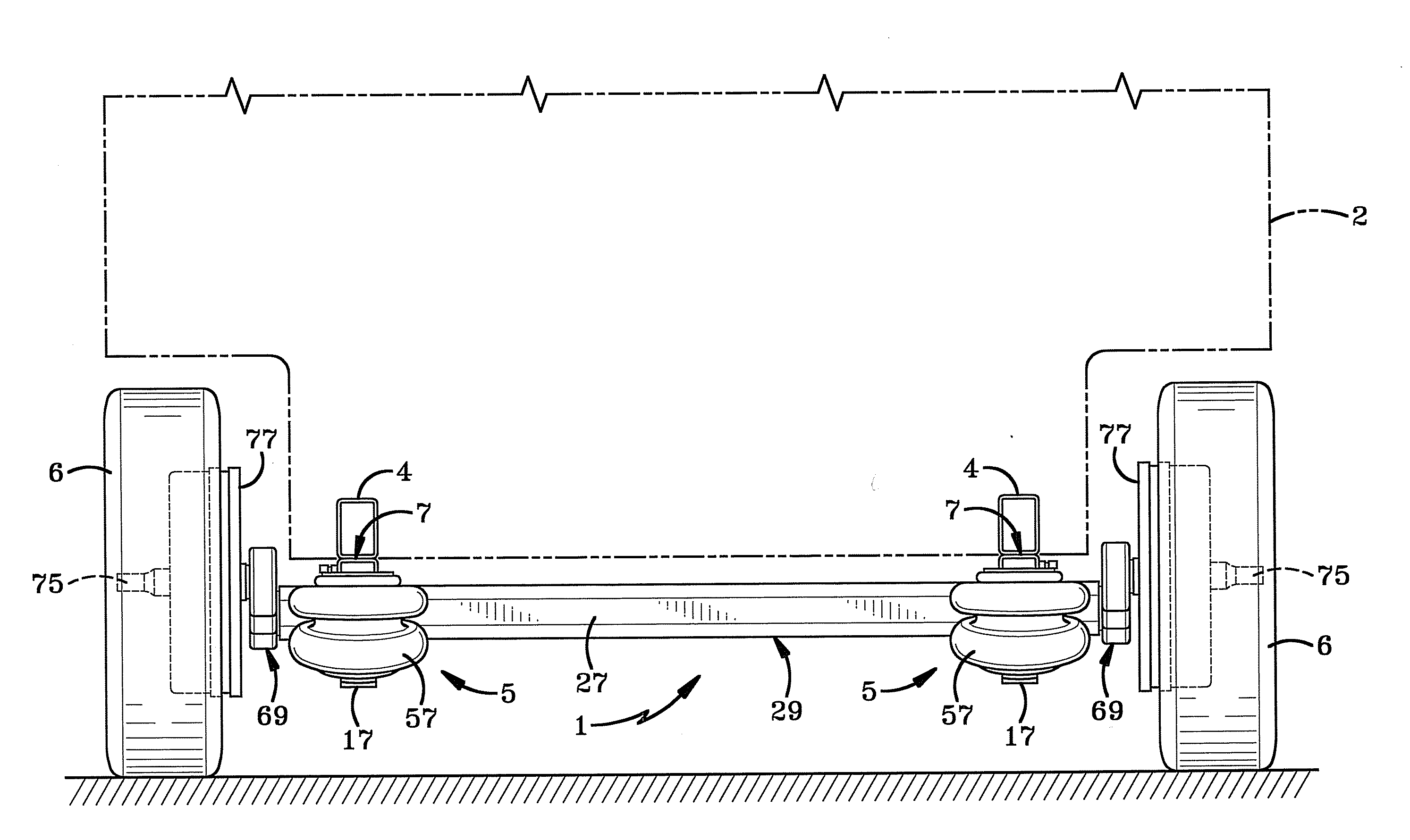
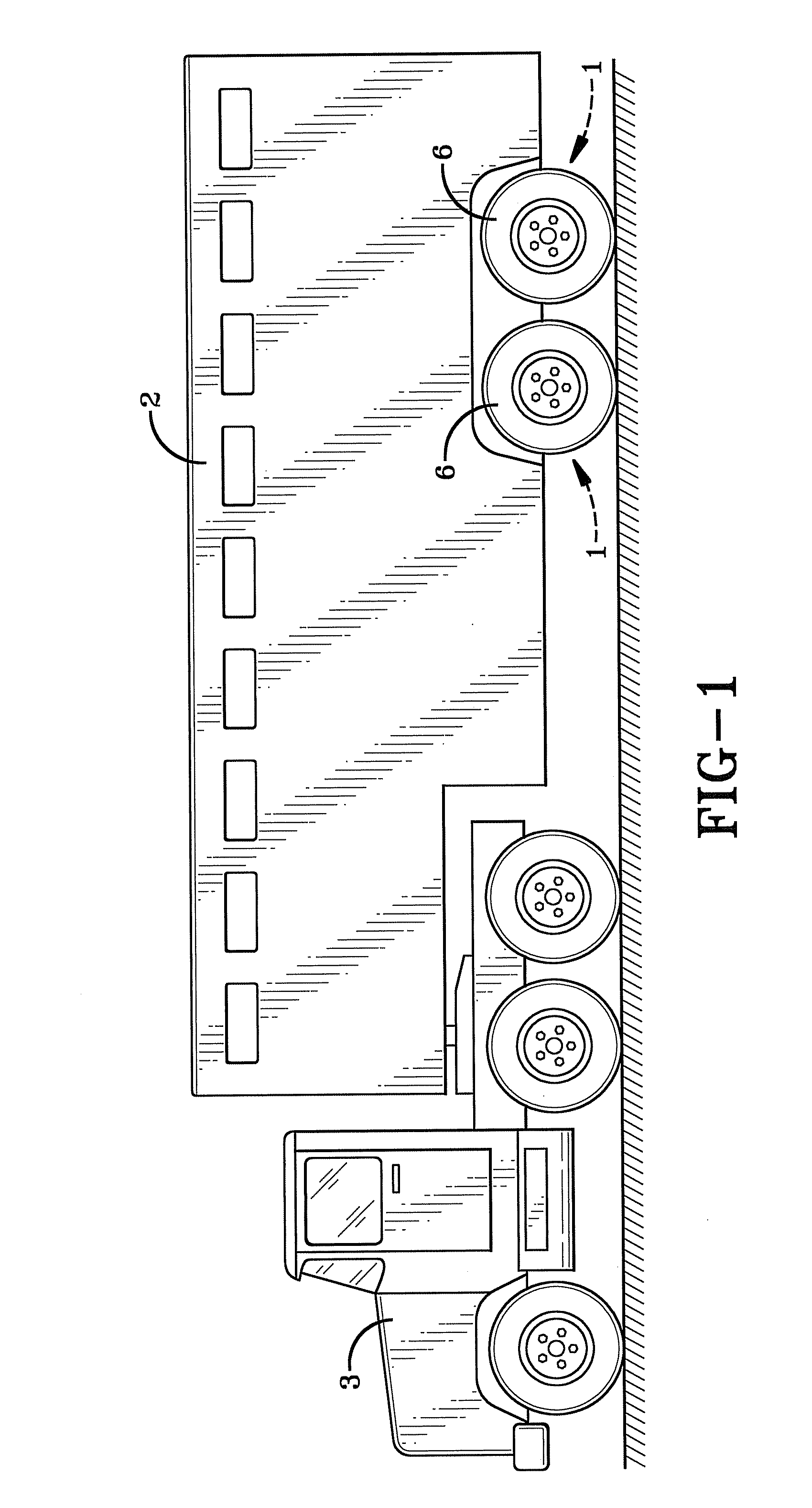
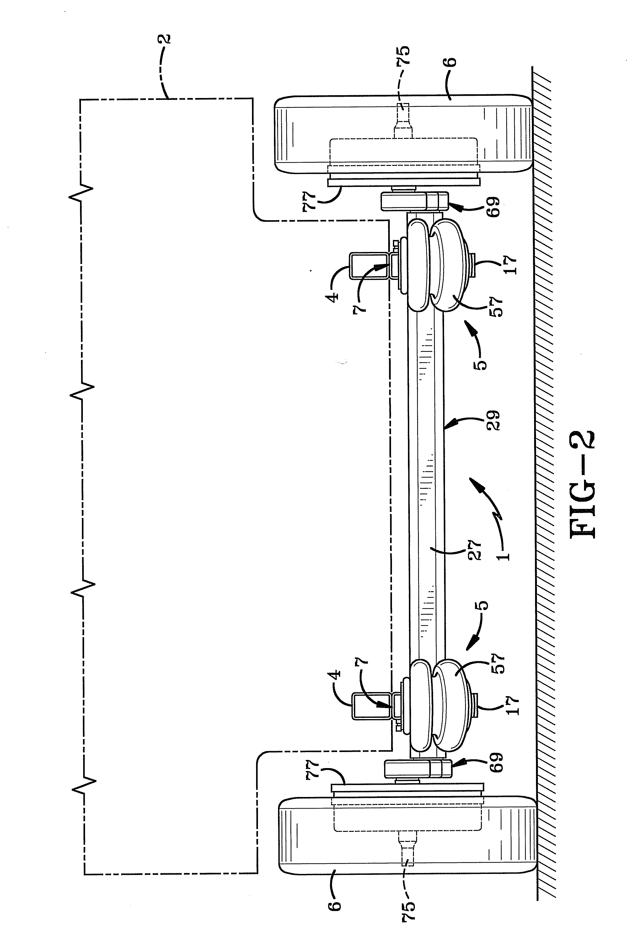
[0032]A vehicle suspension system having the improved suspension assembly of the present invention is indicated generally at 1, and is shown particularly in FIGS. 1-13 mounted on a vehicle 2, such as a trailer of the type being towed by a tractor 3. Trailer 2 is supported on a pair of frame rails 4 extending longitudinally along a length of the trailer (FIG. 2). A pair of the improved suspension assemblies, each indicated generally at 5, is mounted on a respective frame rail 4 generally adjacent a wheel 6. Suspension assembly 5 as best shown in FIG. 3, includes a frame mounting bracket 7 which is secured to one of the trailer frame rails 4 by a plurality of bolts, by welding or other types of attachments. Frame bracket 7 preferably has a U-shaped channel configuration with web wall 9 and a pair of spaced legs 10 terminating at one end in a depending end flange portion 11 (FIGS. 3 and 8) formed by a pair of spaced flange legs 12. Frame bracket 7 may be formed with a central cutout 13...


PUM


Abstract

A vehicle suspension system includes a pair of suspension assemblies mounted on a pair of spaced vehicle frame members for supporting a vehicle body on the vehicle wheels. A torsion axle extends between the pair of suspension assemblies and terminates in a pair of stub shafts. The axle is mounted on a pair of spaced frame brackets attached to the vehicle frame. An air spring extends between the vehicle frame and an outer end of a support arm pivotally mounted on each end of the torsion axle. The stub shafts are supported within an outer tube of the torsion axle by a plurality of elastomeric members. One end of each stub shaft is connected to a spindle arm which has a spindle extending from an opposite end of the arm. The length of the air spring support arm and the distances between the pivot axis of the support arm and the axii of the spindle and torsion axle are chosen so that the surface of the air spring is always out of contact with the mounting bracket and has a portion inboard between the axis of the spindle and axis of the torsion axle.

Description

BACKGROUND OF THE INVENTION[0001]1. Technical Field[0002]The invention relates to suspension systems for vehicles, such as trailers and trucks. More particularly, the invention relates to a suspension assembly having a torsion axle in combination with an air spring. Even more particularly, the invention relates to a more compact, lighter weight combination torsion axle-air spring suspension assembly than known prior art combination suspension assemblies.[0003]2. Background Information[0004]Torsion axles have been known for many years, such as shown in U.S. Pat. No. 2,998,981. Torsion axles have proven to be extremely popular because if one wheel hits a bump or rut, it can react independently of the other wheel, which may not hit a bump or rut at the same time. This torsion axle concept operates to keep a trailer moving as straight as possible behind a towing vehicle and absorbs some of the shock of the road over which it is passing with an independent suspension. This is contrasted ...

Claims


Application Information

Patent Timeline
Patent Type & Authority Applications(United States)
IPC IPC(8): B60G11/18
CPCB60G11/225B60G11/62B60G2200/132B60G2200/31B60G2202/1424B60G2202/152B60G2300/04B60G2204/126B60G2204/143B60G2204/148B60G2204/41B60G2204/4302B60G2204/125
Inventor VANDENBERG, ERVIN K.CROSTON, DAVID H.
Owner TRANSPORTATION TECH
Why Eureka
Try Eureka