
Accessory holder for a chair

a technology for accessory holders and chairs, which is applied in the direction of chairs, machine supports, fishing, etc., can solve the problems of unstable attachment devices, difficult to attach umbrellas in an efficient manner, and inconvenient devices, so as to reduce construction costs, quick secure to the chair, and the effect of reducing labor

Inactive Publication Date: 2007-06-05
SPANOVICH JOSEPH P
View PDF14 Cites 40 Cited by
  • Summary
  • Abstract
  • Description
  • Claims
  • Application Information

AI Technical Summary

Benefits of technology

[0008]It is an object of the invention to provide an accessory holder for a chair that is adapted to support a conventional golf umbrella by securing the device to the leg portion of the chair at two separate attachment points and thereby increase stability of the accessory support device when an umbrella is attached.
[0015]Another object is to provide a simplified clamping structure that spreads the clamping load across the length of the leg of the chair thereby improving clamping strength and reducing failure.

Problems solved by technology

The prior art devices are not satisfactory if a large umbrella is secured to the chair because such umbrellas will render the attachment device unstable due to cantilever forces caused by wind acting on the umbrella and the weight of the umbrella.
Further, prior art clamp members for chairs are known to have a complicated construction that makes it difficult to attach the umbrella in an efficient manner.
The screws associated with such clamps are subjected prematurely to wear and failure.
In addition, clamps employing screws are known to damage the chair frame because of the high grip forces required for attachment.
Prior art accessory holders are typically constructed from metal materials because screws are used in the clamps; however, such devices do not provide a secure anchor for the umbrella and are subjected to rusting and eventual failure.
None of the prior art devices are adapted to receive a golf umbrella or similarly large and heavy umbrella that is unwieldy and therefore difficult to secure to a chair in a fixed manner.
Finally, none of the prior art devices are known to secure an umbrella to the chair whereby the attachment can be made to the leg portion of the chair.
In the case of folding chairs, all of the prior art devices must be removed from the chair prior to folding and cannot remain secured to the chair when it is in a folded position.

Method used


Image

  • Accessory holder for a chair
  • Accessory holder for a chair
  • Accessory holder for a chair

Examples


Embodiment Construction

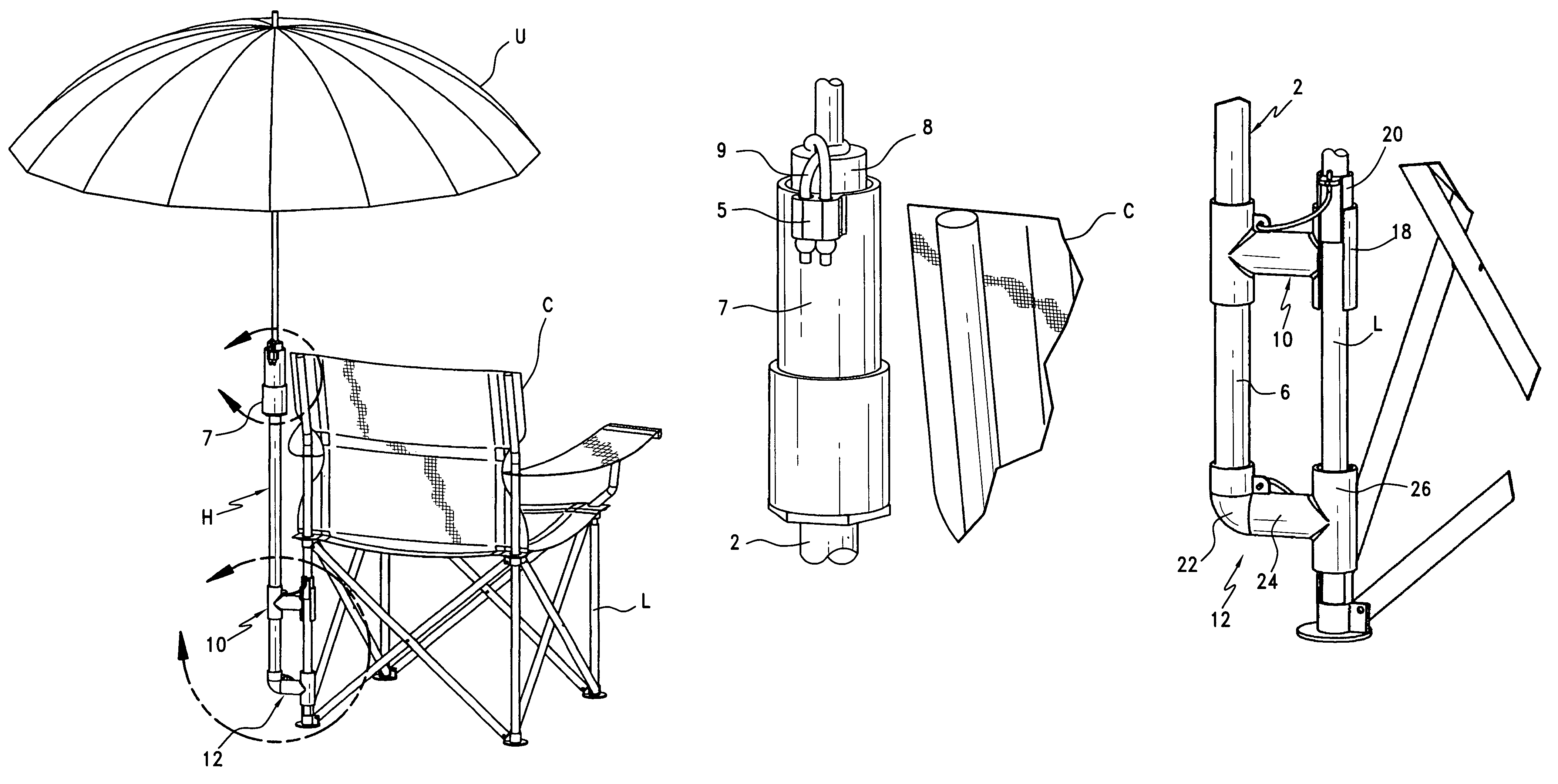
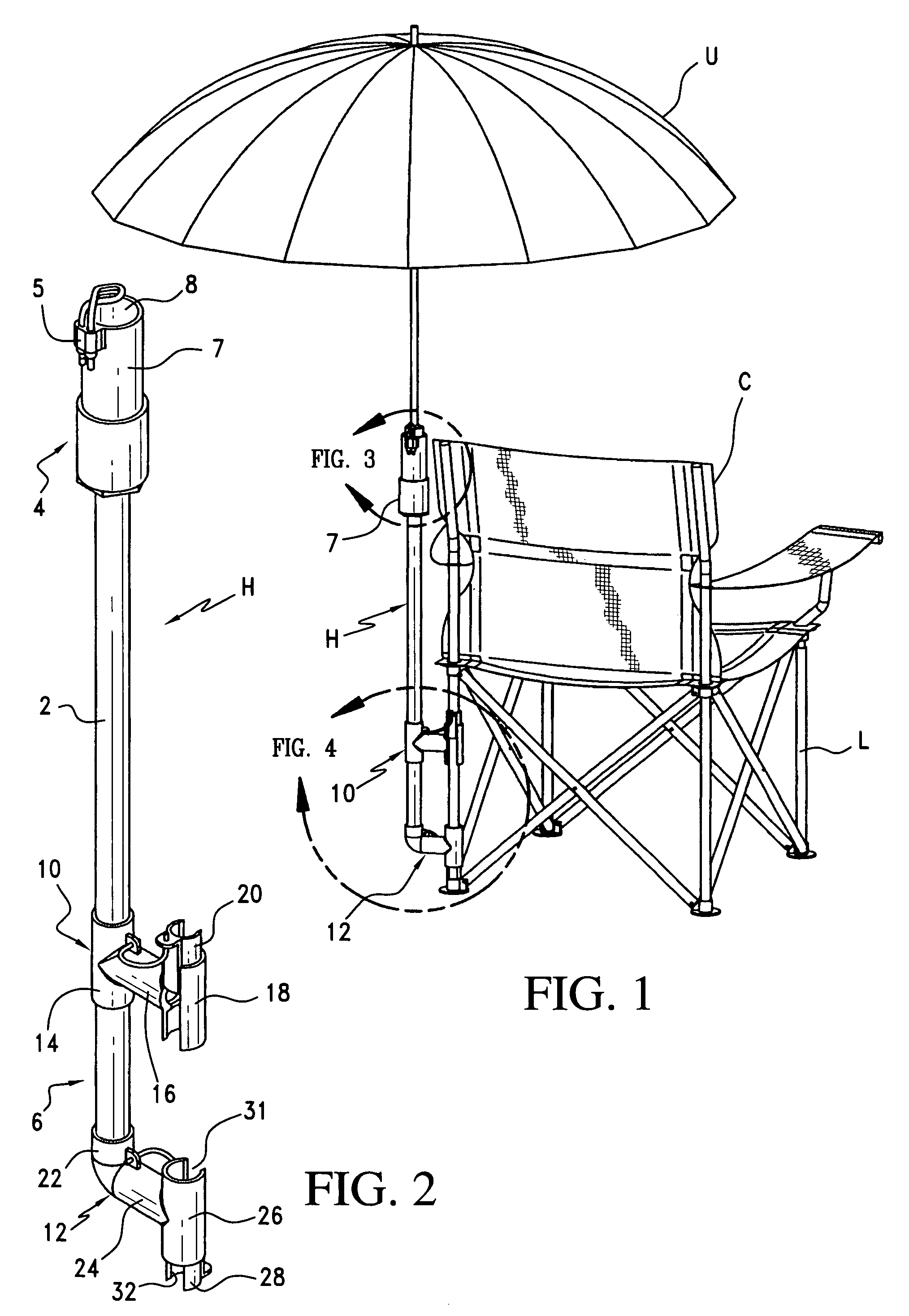
[0026]FIG. 1 illustrates a first embodiment of the present invention and shows the accessory holder H attached to a leg L of folding chair C with an umbrella U secured within the holder H. It is of course within the scope of the present invention to secure the accessory holder to a non-folding chair with little to no modification.

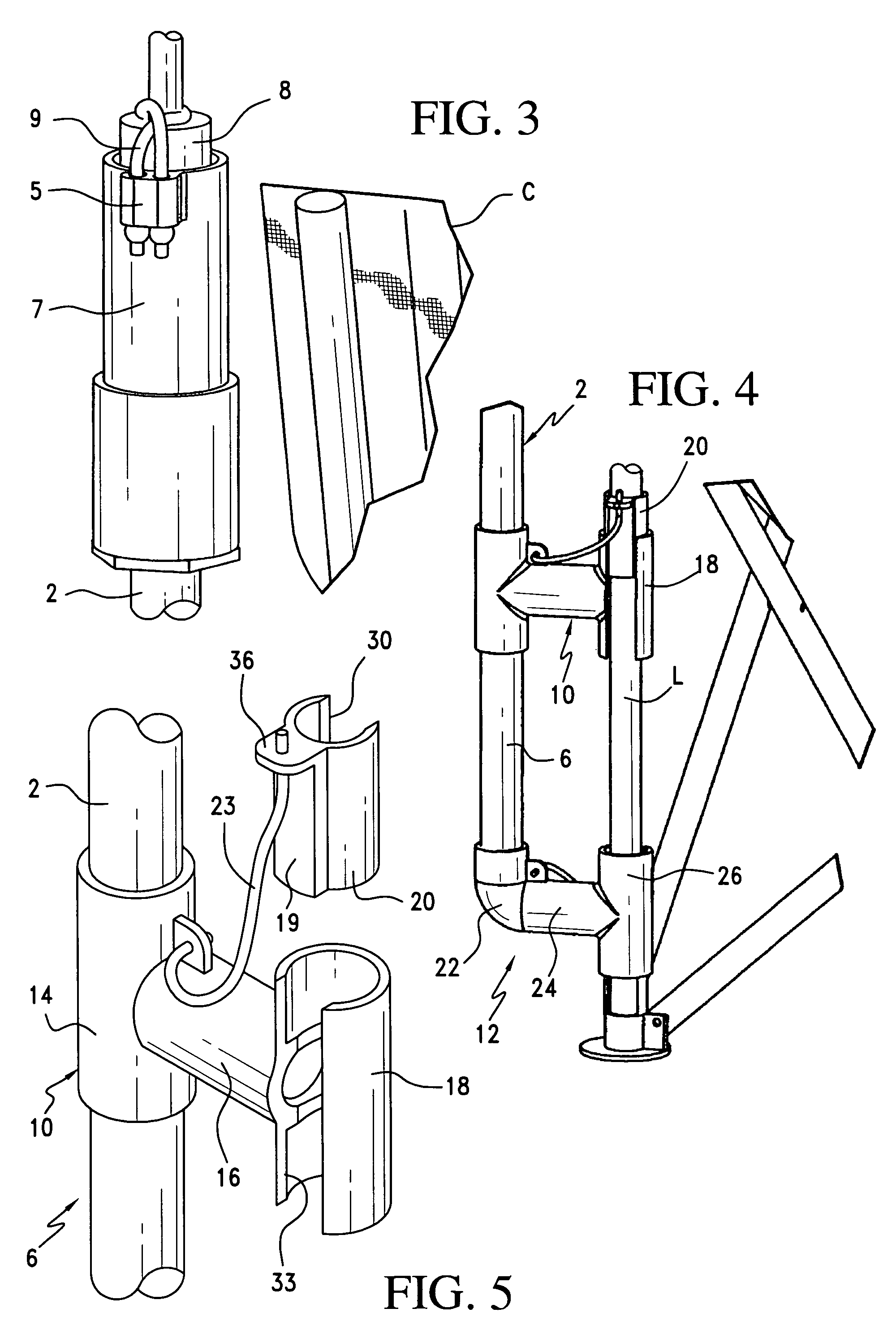
[0027]As best shown in FIG. 2, the accessory holder H generally comprises a support member 2 having a first or upper end 4 and an opposite second or lower end 6. FIG. 3 shows the upper end 4 of support member 2 to be provided with a receptacle or socket 7 having an opening adapted to receive a golf umbrella handle 8. The socket 7 for receiving the handle 8 includes a cord attachment lug 5 with cooperating elastic shock cord 9 for securing the handle 8 within the socket 7. As is apparent, other arrangements for securing the handle within a socket or to the end of the support member 2 are within the scope of the present invention.

[0028]FIG. 4 illustrates the ...


PUM


Abstract

An accessory holder for a chair comprising of a support arm having a first end and second end, the first end is adapted for connection to an accessory such as an umbrella or tray, at least one locking member extending from the support arm second end, at least one locking member comprising a pair of cooperating sleeve members adapted to be slidingly engaged in a concentric manner, one of the cooperating sleeves is adapted to be disposed around a leg of a chair whereby when the other cooperating sleeve members is slidingly engaged in a concentric manner with one of the pair of cooperating sleeves, the support arm is secured to the chair.

Description

FIELD OF THE INVENTION[0001]The present invention relates to devices for securing an umbrella or other accessory to a chair.BACKGROUND OF THE INVENTION[0002]It is known to attach an umbrella to a chair to provide shade and protection. It is similarly known to secure a tray or cup holder to a chair. These attachment devices eliminate the need for having to hold an umbrella or tray while seated and thereby free up the use of one's hands.[0003]Prior art attachment devices are usually secured to the upper portion of the chair with a single clamp having a screw or wing nut that tightens the clamp to the frame of the chair.[0004]The prior art devices are not satisfactory if a large umbrella is secured to the chair because such umbrellas will render the attachment device unstable due to cantilever forces caused by wind acting on the umbrella and the weight of the umbrella. Further, prior art clamp members for chairs are known to have a complicated construction that makes it difficult to at...

Claims


Application Information

Patent Timeline
IPC IPC(8): A47C29/00
CPCA47C7/66A45B2200/1063A47C4/286A47C7/664A47C7/62
Inventor SPANOVICH, JOSEPH P.
Owner SPANOVICH JOSEPH P
Learn More