Plug connector

Inactive Publication Date: 2007-06-05
JESS-LINK PRODUCTS
View PDF6 Cites 27 Cited by
  • Summary
  • Abstract
  • Description
  • Claims
  • Application Information

AI Technical Summary

Benefits of technology

[0007]It is therefore a main object of the invention to provide a plug connector, which has an engagement mechanism for engaging with a mating con

Problems solved by technology

Because of the rapid development of technology, data tra

Method used


Image

  • Plug connector
  • Plug connector
  • Plug connector

Examples


Example

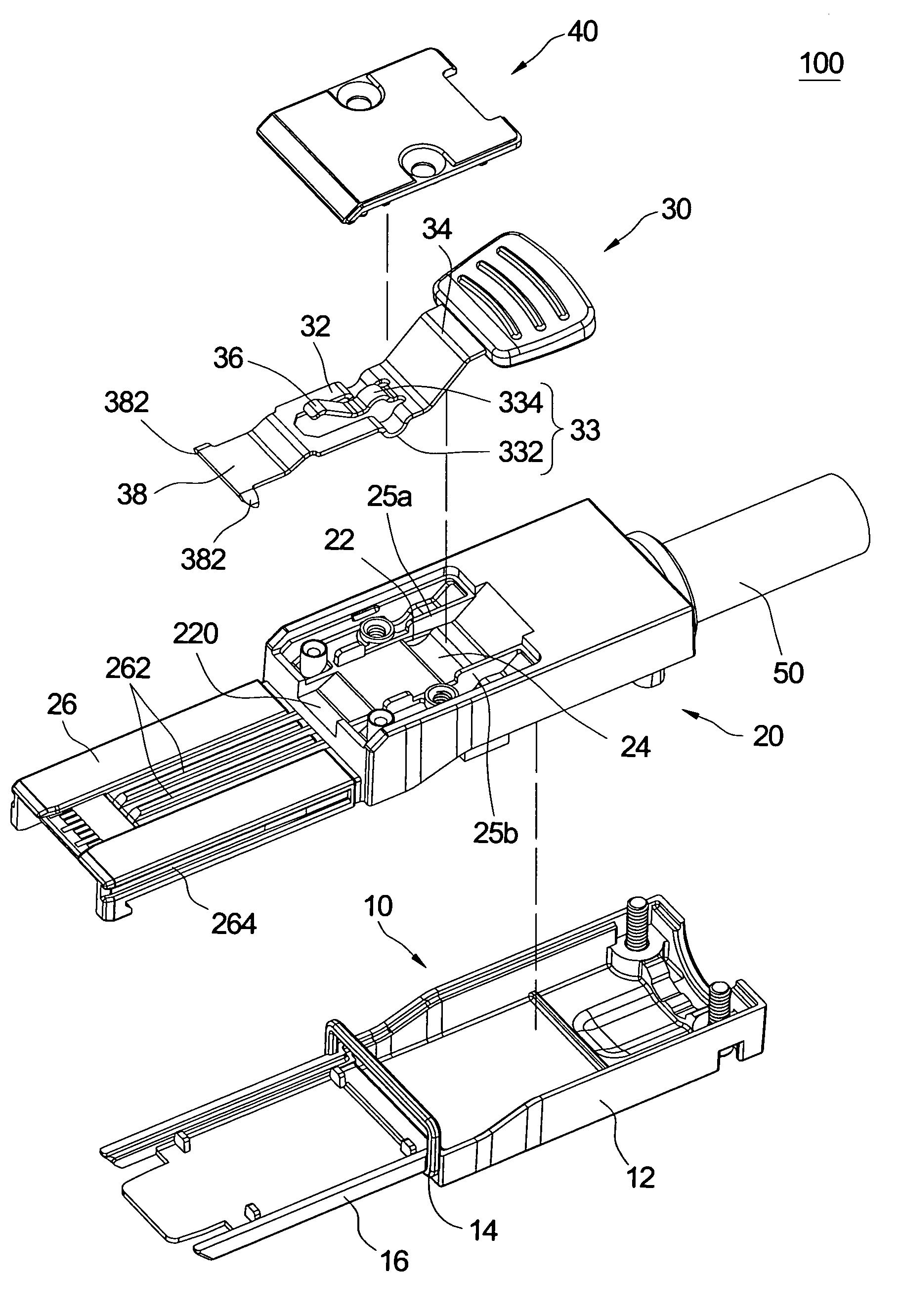
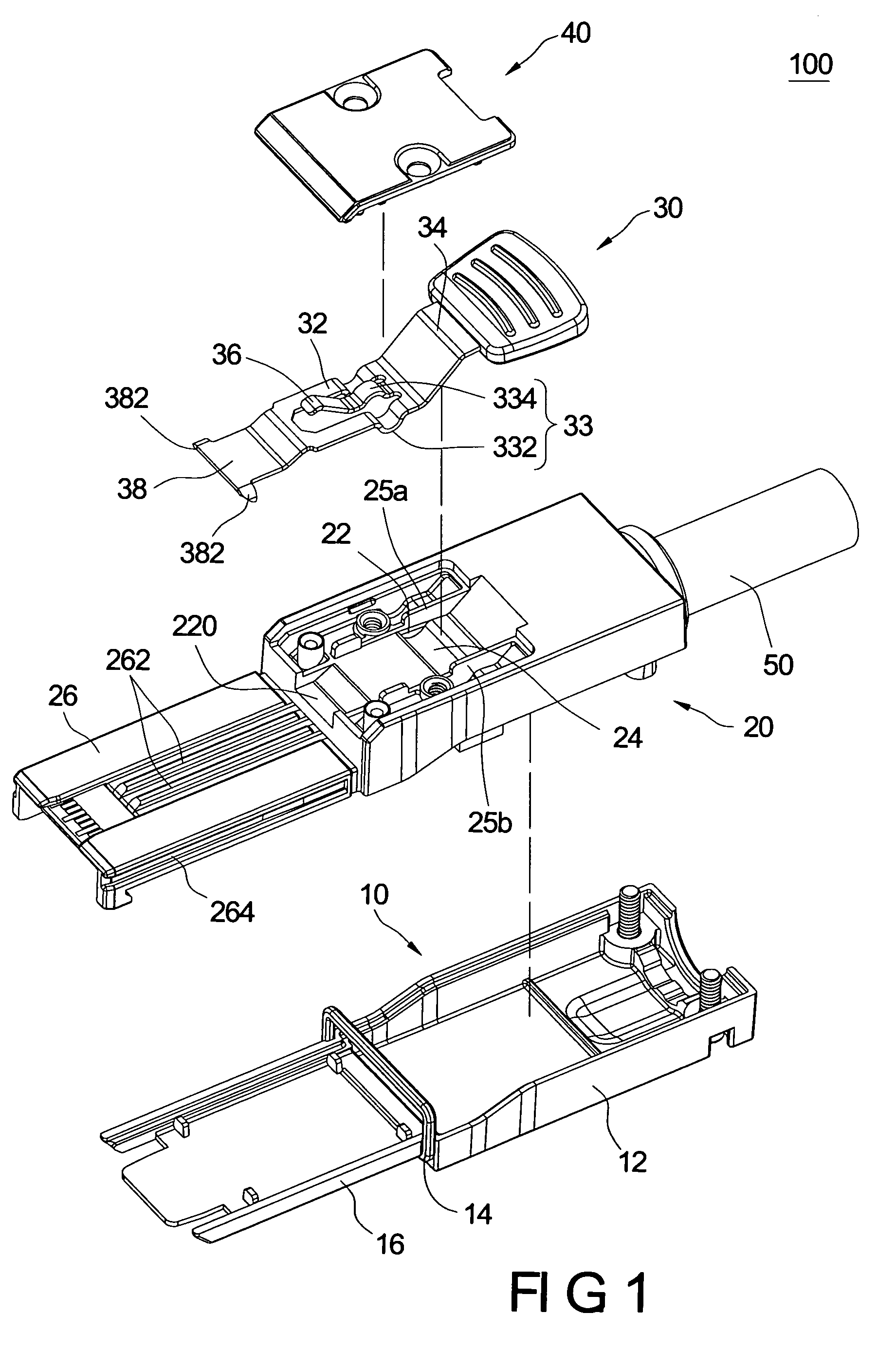
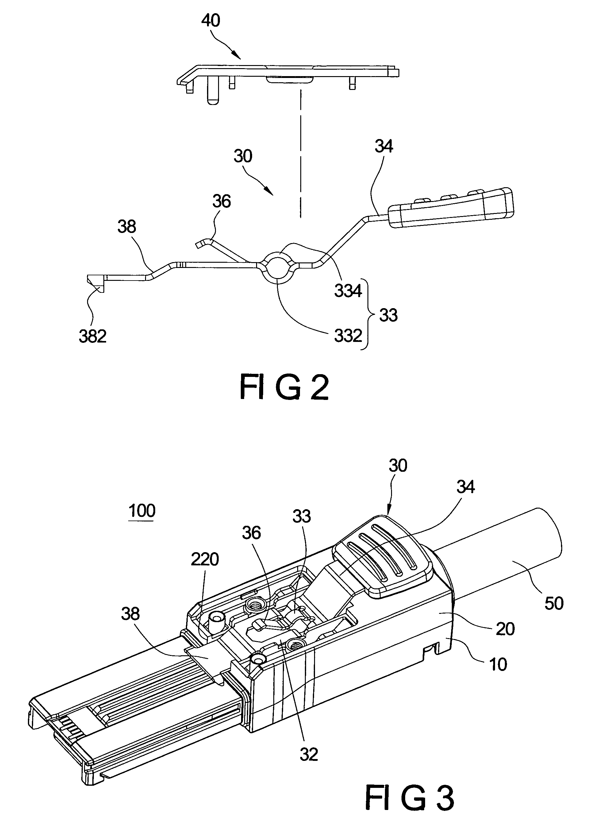
[0017]Reference is made to FIG. 1, which is an explored perspective view of a plug connector of the present invention. The present invention provides a plug connector 100, which could be engaged with a mating connector 200 as shown in FIG. 5. The plug connector 100 includes a lower housing 10, a upper housing 20, a disengaged member 30 and a covering lid 40. The plug connector 100 connects with a cable 50 at its rear end. The upper housing 20 combines with the lower housing 10 to form a housing. The housing receives a circuit board therein and the wires of the cable 50 are soldered on the circuit board. In this embodiment, the plug connector is a Small Form Factor Pluggable (SFP) connector.

[0018]The upper housing 20 has a receiving cavity 22 concaved from a top surface thereof, a pivotal groove 24 disposed in the receiving cavity 22, and a pair of positioning boards 25a, 25b protruded upwardly in the receiving cavity 22. The upper housing 20 extends a upper shielded portion 26 from ...


PUM


Abstract

A plug connector for plugging with a mating connector includes a lower housing, an upper housing fixed on the lower housing, a disengaged member and a covering lid. The upper housing has a receiving cavity concaved from its top surface and a pivotal groove formed in the receiving cavity. The disengaged member has a main body, an elastic member disposed on the main body, a handle portion extending and inclining upwardly from the main body, and a hooking plate extending from the main body. The hooking plate is opposite to the handle portion and is exposed outside the upper housing. The main body forms a rod-shaped portion disposed movably in the pivotal groove. The hooking plate hooks elastically the mating connector. The covering lid is fixed on the upper housing and covers the receiving cavity. The elastic member is propped against a bottom surface of the covering lid.

Description

BACKGROUND OF THE INVENTION[0001]1. Field of the Invention[0002]The present invention relates to a plug connector, and more particularly to a small size connector having an engagement mechanism for engaging with a mating connector or disengaging from the mating connector.[0003]2. Description of Related Art[0004]Because of the rapid development of technology, data transferring requirement is more and more huge and rapidly. High speed data transfer systems require electrical connectors in which the electrical impedance ca be controlled in order to maintain the required data transfer rate of the electrical system.[0005]Electrical connector is usually composed of a plug connector and a mating connector. The requirements for electrical connectors are not only smaller size, but also stable engagement between both. Therefore, in this field there is an essential need for plug connectors of smaller size in a prerequisite condition, wherein a stable engagement is necessary for engaging with t...

Claims


Application Information

Patent Timeline
IPC IPC(8): H01R13/627
CPCH01R13/6275
Inventor CHEN, SHI-JUNGCHEN, CHUN-HSU
Owner JESS-LINK PRODUCTS
Why Eureka
Try Eureka