Brake lock for line brake and line brake bicycle

A wire brake brake lock and brake lock technology, which is applied in the field of rickshaw and rickshaw locks, can solve the problems of heavy bicycle locks, troublesome locking and unlocking procedures, and the inability to prevent violent cutting of lock ropes or lock cylinders, etc., and achieves simplified locking and unlocking Program, increase the difficulty of stealing, simple and reliable structure

Inactive Publication Date: 2016-08-03
杨先哲
View PDF0 Cites 7 Cited by
  • Summary
  • Abstract
  • Description
  • Claims
  • Application Information

AI Technical Summary

Problems solved by technology

[0004] The technical problem to be solved by the present invention is that the bicycle locks of the prior art cannot prevent thieves from using tools such as hydraulic shears

Method used


Image

  • Brake lock for line brake and line brake bicycle
  • Brake lock for line brake and line brake bicycle
  • Brake lock for line brake and line brake bicycle

Examples


Embodiment 1

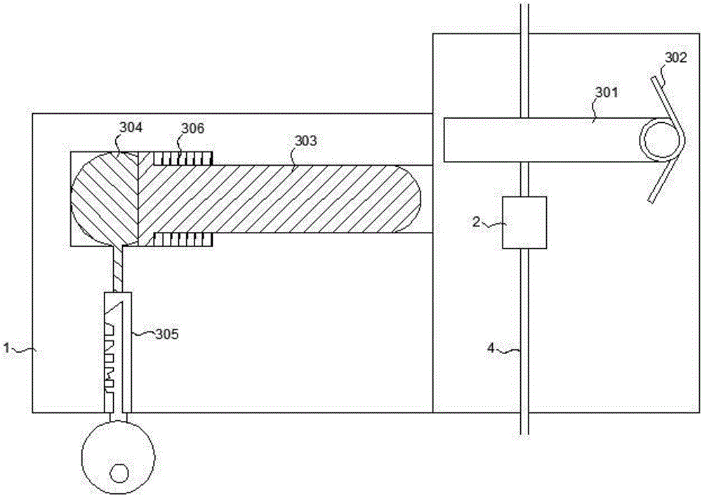
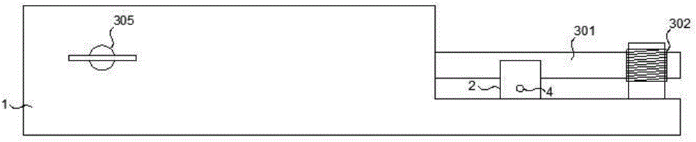
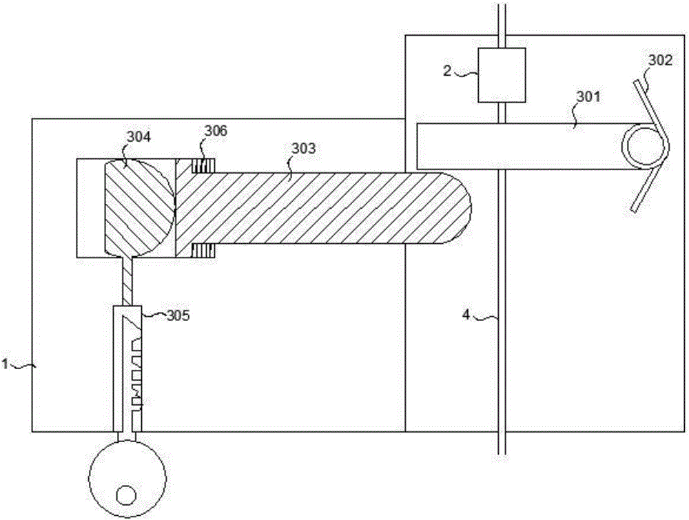
[0031] Such as Figure 1 to Figure 4 As shown, the wire brake lock of this embodiment includes a lock body 1, a brake block 2 and a locking structure 3, the brake block 2 and the locking structure 3 are installed in the lock body 1, and the brake block 2 and the brake rope 4 Fixedly connected, the brake block 2 can slide along the direction of the brake rope 4 in the lock body 1 .

[0032] The locking structure 3 includes a rotating block 301, a torsion spring 302, a first limiting block 303, a cam 304, a lock core 305 and a spring 306, one end of the rotating block 301 is connected to the torsion spring 302, and the rotating block 301 can be twisted The spring 302 rotates, the rotating block 301 is located on the sliding path of the brake block 2 ; the first limiting block 303 is located in the slide groove of the lock body 1 . The lock core 305 and the cam 304 are located in the lock body 1, and the lock core 305 is connected to the cam 304; one end of the first limiting bl...

Embodiment 2

[0036] Such as Figure 5 to Figure 8 As shown, the wire brake lock of this embodiment includes a lock body 1, a brake block 2 and a locking structure 3, the brake block 2 and the locking structure 3 are installed in the lock body 1, and the brake block 2 and the brake rope 4 Fixedly connected, the brake block 2 can slide along the direction of the brake rope 4 in the lock body 1 .

[0037]The locking structure 3 includes a rotating block 301, a torsion spring 302, a first limiting block 303, a first electromagnet 307, a first spring 308, a second electromagnet 309, a second spring 310 and a locking block 311. One end of the block 301 is connected with the torsion spring 302 , the rotating block 301 can rotate around the torsion spring 302 , the rotating block 301 is located on the sliding path of the braking block 2 ; the first limiting block 303 is located in the slide groove of the lock body 1 . The first spring 308 is located between the first electromagnet 307 and the fir...

Embodiment 3

[0042] Such as Figure 9 with Figure 10 As shown, the wire brake lock of this embodiment includes a lock body 1, a brake block 2 and a locking structure 3, the brake block 2 and the locking structure 3 are installed in the lock body 1, and the brake block 2 and the brake rope 4 Fixedly connected, the brake block 2 can slide along the direction of the brake rope 4 in the lock body 1 .

[0043] The locking structure 3 includes a third electromagnet 312, a third spring 313, a fourth electromagnet 314, a fourth spring 315, a second limiting block 316 and a locking block 311, the third electromagnet 312, the third spring 313 and the second limiting block 316 are sequentially connected, the outer end of the second limiting block 316 is provided with a slope, and the brake block 2 is provided with a slope corresponding to the slope of the second limiting block 316; the side of the second limiting block 316 A locking hole is provided, the locking block 311 is located on the side of...


PUM


Abstract

The invention discloses a wire brake lock and a wire brake bicycle. The wire brake lock includes a lock body, a brake block and a locking structure. The brake block and the lock structure are installed in the lock body. The brake block and the brake rope Fixed connection, the brake block can slide or rotate in the lock body to pull the brake rope to brake and release the wheel, the locking structure can lock the brake block or release the brake block under the action of external force, the brake lock is locked in the bicycle brake When the brake rope is locked under normal circumstances, all parts of the brake lock are located in the lock body, and the thief cannot use hydraulic shears to violently cut the lock, which greatly increases the difficulty of stealing for the thief; the wire brake bicycle of the present invention is installed on the Disc brakes, and the brake rope is connected to the bicycle support shaft, and the user can lock the bicycle by the action of putting down the bicycle support, which is convenient for the user.

Description

technical field [0001] The invention relates to the field of rickshaws and rickshaw locks, in particular to a wire-brake lock and a wire-brake bicycle. Background technique [0002] Bicycle is a simple in structure, reliable in performance and low in price, and is an environmentally friendly means of transportation. It can be seen in all countries in the world. Bicycles are used outdoors, and the characteristics of stopping and using make bicycles easy targets for thieves. If bicycle users cannot park their bicycles in a safe, reliable, and strictly monitored area, the anti-theft measures for bicycles can only rely on bicycle locks. [0003] Although there are many types of bicycle locks at present, the principle of bicycle locks generally has two types: one is to use steel ropes or steel columns to encase the wheels to prevent the rotation of bicycle wheels; This type of lock locks the bicycle to a fixed object and prevents the bicycle from moving. These current bicycle ...

Claims


Application Information

Patent Timeline
IPC IPC(8): B62H5/18B62L1/02
CPCB62H5/18B62L1/02
Inventor 杨先哲郑启航王子祎黄天辰
Owner 杨先哲
Why Eureka
Try Eureka