Limiting mechanism for board card

A technology of restricting mechanisms and boards, which is applied to the parts of the connecting device, electrical components, coupling devices, etc., can solve the problems of illegally stealing the memory card, shaking contact, bad, etc., and achieves good fixing effect and is not easy to remove. Avoid shaking effects

Active Publication Date: 2011-05-11
ASUSTEK COMPUTER INC
View PDF0 Cites 0 Cited by
  • Summary
  • Abstract
  • Description
  • Claims
  • Application Information

AI Technical Summary

Problems solved by technology

However, due to this design, there is still a displaceable space between the insert and the socket, and this displaceable space will cause the memory card to be unable to be stably fixed in the socket, resulting in shaking or poor contact.
In addition, since the memory card inserted in the socket can be easily removed by simply pulling the latch, the unscrupulous user can steal a large number of memory cards in a short time

Method used


Image

  • Limiting mechanism for board card
  • Limiting mechanism for board card
  • Limiting mechanism for board card

Examples


Embodiment Construction

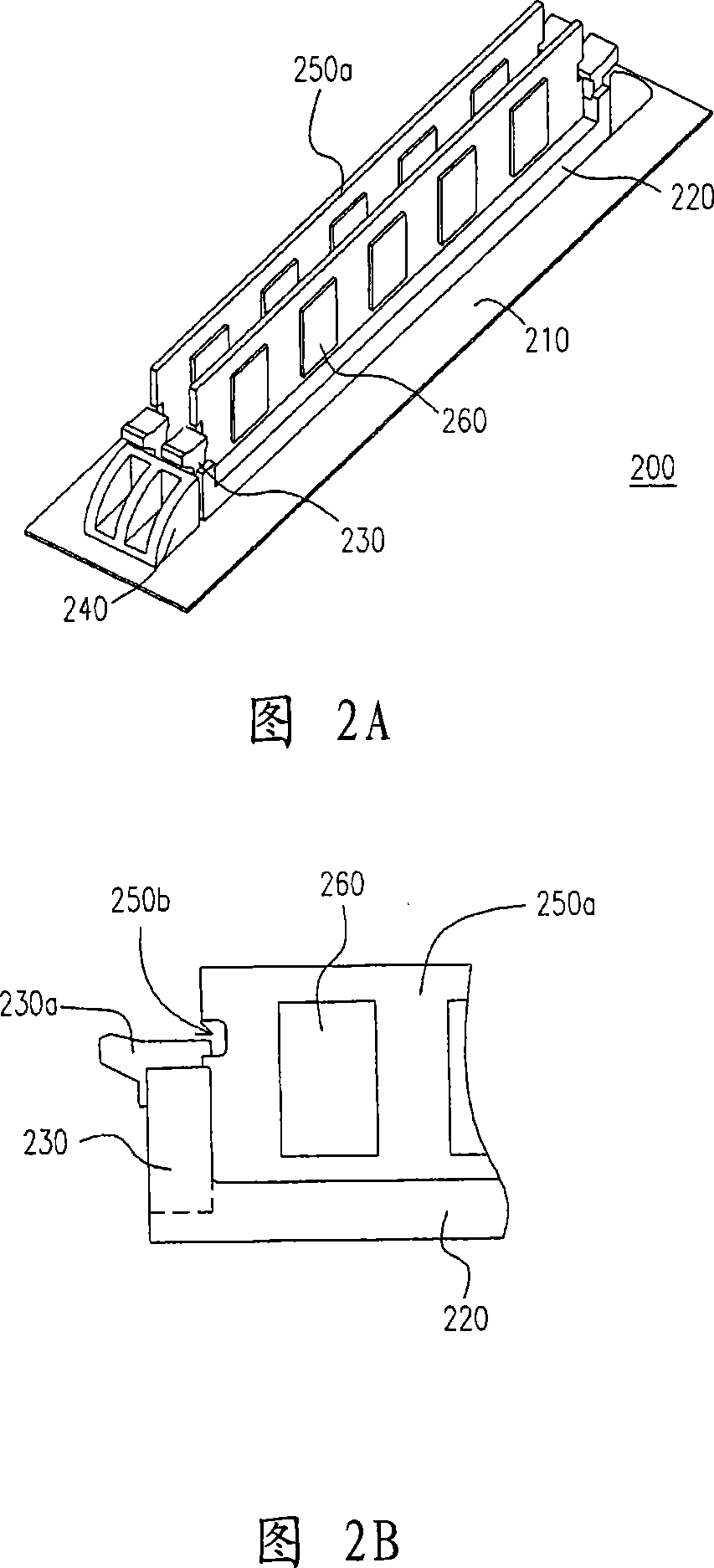
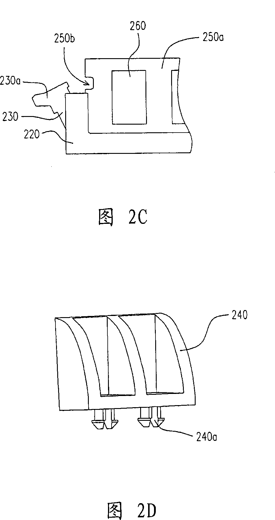
[0031] FIG. 2A is a schematic diagram of the limiting structure of the board of the first embodiment of the present invention. Please refer to FIG. 2A, in this embodiment, the limiting mechanism 200 of the board includes a substrate 210, a socket seat 220, a buckle 230 and a limiting member 240, wherein the board 250a is equipped with at least one electronic Element 260. A board 250 a is inserted into the slot seat 220 , and the buckle 230 is rotatably pivoted on one side of the slot seat 220 for fixing the board card 250 a in the slot seat 220 . The limiting member 240 is used to prohibit the rotation of the buckle 230 so as to provide a good fixing effect for the card 250a.

[0032] In detail, the substrate 210 of the card limiting mechanism 200 may be a circuit board, which can be electrically connected to the substrate 210 when the card 250 a is inserted into the socket 220 . In addition, the slot seat 220 of the limiting mechanism 200 of the card is, for example, for a ...


PUM


Abstract

The invention relates to a limiting mechanism of a plate clip, wherein at least electronic component is arranged on the plate clip; the limiting mechanism of the plate clip comprises a substrate, a slot seat, a fastening button and a limiting piece. The slot seat is used for the plate clip to insert. The fastening button can be rotatably pivoted on one side of the slot seat. When the fastening button rotates to a first position, the plate clip is clipped in the slot seat; when the fastening button rotates to a second position, the plate clip is allowed to be separated from the slot seat. The limiting piece is used for forbidding the fastening button to rotate to the second position.

Description

technical field [0001] The present invention relates to a limiting mechanism, and in particular to a limiting mechanism of a board. Background technique [0002] The known memory card fixing device is used to fix a memory card on a circuit board, so that the memory card can be electrically connected to other electronic components through the circuit board to achieve the transmission of data signals. [0003] FIG. 1A is a schematic diagram of a known memory card fixing device. Please refer to FIG. 1A, the known memory card fixing device 100 is composed of a slot base 120 and latches 150 pivotally arranged on both sides of the slot base 120, wherein a circuit board 110 is arranged at the bottom of the slot base 120, and The socket socket 120 is capable of inserting the memory card 130 . [0004] FIG. 1B is a schematic diagram of a memory card detaching from a known memory card fixing device. Please refer to FIG. 1A and FIG. 1B at the same time. In the known technology, the s...

Claims


Application Information

Patent Timeline
Patent Type & Authority Patents(China)
IPC IPC(8): H01R13/639H01R13/629H01R12/73
Inventor 吴潮崇李侑澄
Owner ASUSTEK COMPUTER INC
Why Eureka
Try Eureka