Self-correcting rear projection television

a rear projection television and self-correction technology, applied in the field of rear projection televisions, can solve the problems of blurred projected images, objectionable color fringe artifacts, and difficulty in maintaining convergen

Inactive Publication Date: 2007-06-05
MITSUBISHI ELECTRIC RES LAB INC
View PDF17 Cites 20 Cited by
  • Summary
  • Abstract
  • Description
  • Claims
  • Application Information

AI Technical Summary

Problems solved by technology

If these distortions are not corrected or “converged,” then the projected images are blurred and have objectionable color fringe artifacts.
However, due to physical, electrical, optical, and magnetic factors, it is often difficult to maintain convergence over time.
At best the locations are at an extreme periphery of the projected image because placing the detectors on the screen would interfere with the projected images.

Method used


Image

  • Self-correcting rear projection television
  • Self-correcting rear projection television
  • Self-correcting rear projection television

Examples


Embodiment Construction

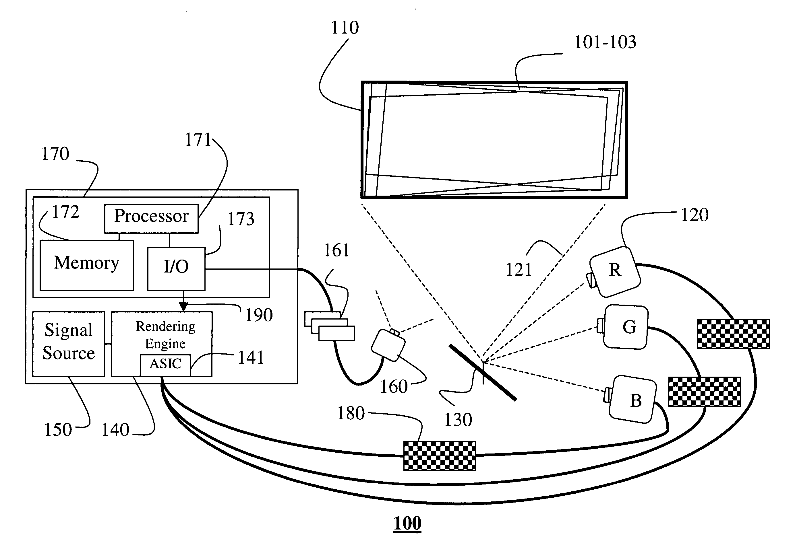
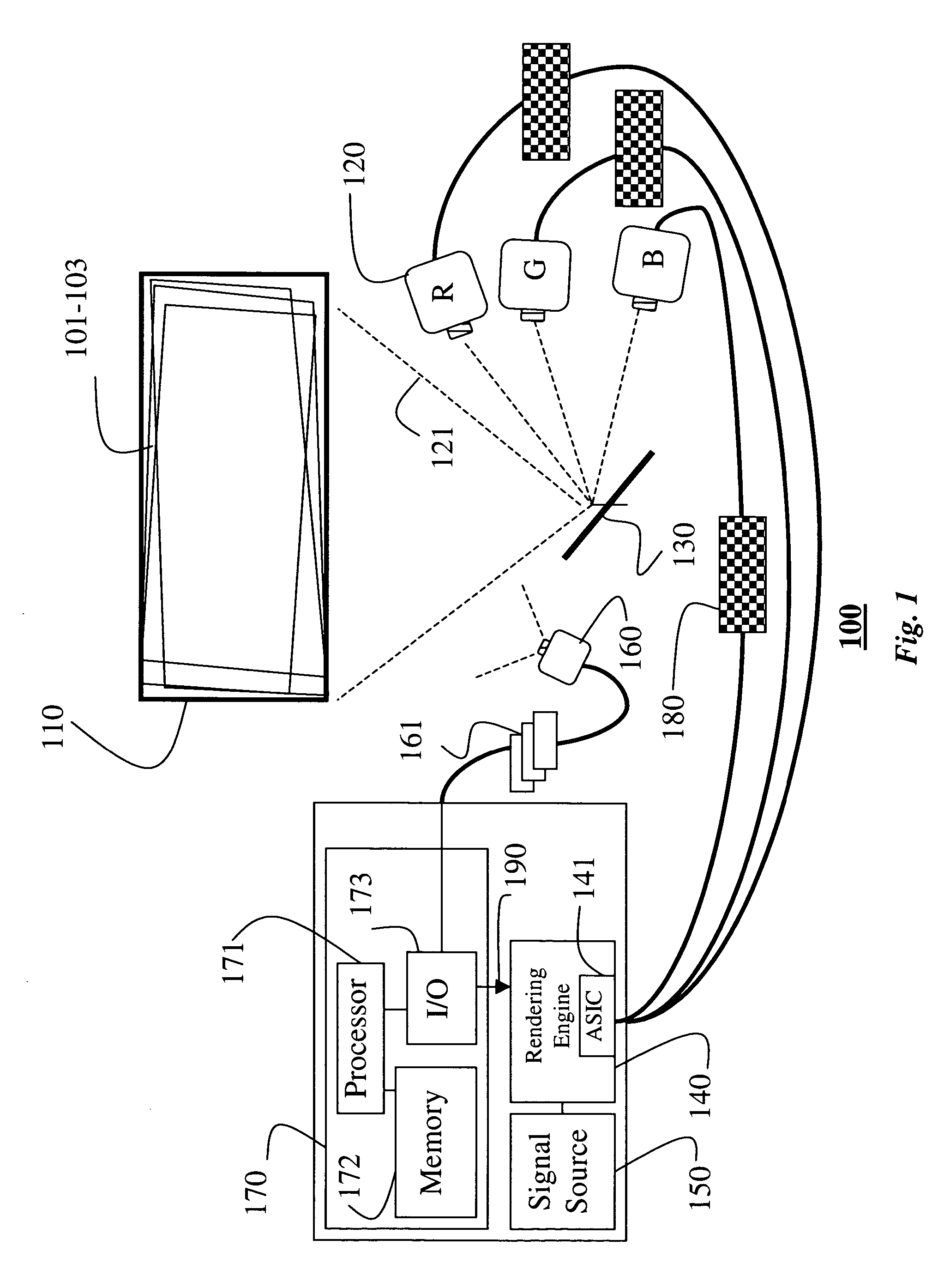
[0019]FIG. 1 shows a self-convergent projection television (PTV) 100 according to our invention. Three images 101–103 are projected onto a rear projection screen 110 by three CRTs 120 (RGB). Each CRT produces images consisting of an n×m array of pixels, which determine an aspect ratio of the images.

[0020]The images 101–103 are usually projected via a mirror 130 to increase the size of the projected images 101–103 by lengthening the optical paths 121. The images can be generated by a rendering engine 140. The rendering engine can be in the form of a raster generator, graphics hardware card, or a an application specific integrated circuit (ASIC) 141. The rendering engine can be coupled to a signal source 150, such as, a television receiver, video player, graphics hardware, computer, and the like, as known in the art.

[0021]The PTV also includes a computer system 170 comprising a processor 171, memory 172, and I / O interface 173 connected by buses to each other and the rendering engine 1...


PUM


Abstract

In a rear projection television, cathode ray tubes are mounted inside an enclosure so that each cathode ray tube projects output images onto a rear projection screen using a corresponding electron beam. Calibration images are generated for each cathode ray tube. A camera, also mounted inside the enclosure, acquires an input image of each calibration image. A distortion in each input image is measured, and the output images of the cathode ray tubes are corrected by adjusting the signals controlling the corresponding electron beams according to the distortion.

Description

FIELD OF THE INVENTION[0001]This invention relates generally to rear projection televisions, and more particularly to correcting convergence errors in CRT-based projection televisions.BACKGROUND OF THE INVENTION[0002]In a CRT-based projection television (PTV), three CRTs project colored (RGB) images onto a rear projection screen. Typically, the images are reflected by a mirror, which lengthens the optical path to produce a larger output image. Because the three CRTs are positioned at three different locations, the projected images can be distorted in various ways. If these distortions are not corrected or “converged,” then the projected images are blurred and have objectionable color fringe artifacts.[0003]Typically, convergence errors are measured and corrected at the factory prior to distribution. However, due to physical, electrical, optical, and magnetic factors, it is often difficult to maintain convergence over time. Many prior art PTV's provide manual adjustment to fine tune ...

Claims


Application Information

Patent Timeline
Patent Type & Authority Patents(United States)
IPC IPC(8): H04N9/28H04N3/23H04N9/31H04N5/74H04N17/00H04N17/04
CPCH04N5/7408H04N9/28H04N9/31H04N17/04
Inventor WATERS, RICHARD C.THORNTON, JAY E.RASKAR, RAMESHKATO, MAMORUDIETZ, PAUL H.
Owner MITSUBISHI ELECTRIC RES LAB INC
Why Eureka
Try Eureka