Sheet for use for projection screen, light diffusion sheet and projection screen

a technology of projection screen and light diffusion sheet, which is applied in the direction of instruments, projectors, optics, etc., can solve the problems of difficult continuous production, difficult operation of handling, and difficult image for viewer to s

Inactive Publication Date: 2002-11-14
DAI NIPPON PRINTING CO LTD
View PDF8 Cites 51 Cited by
  • Summary
  • Abstract
  • Description
  • Claims
  • Application Information

AI Technical Summary

Problems solved by technology

This raised the basic problem that the image is very difficult for the viewer to see.
However, since the above-described projection screen necessitates two sheets of lens systems, it is necessary to provide two production lines for manufacturing those respective lenses and, in addition, the operations for handling could not help becoming complicated.
Also, since using a circular Fresnel lens or a circular-arc-like prism, there is the problem that continuous production is difficult.
However, that results in that by the sheet surface having formed thereon the light diffusion fine particles or the concavities and convexities the image light has been randomly reflected to cause the occurrence of many stray lights, followed by deterioration in the surface brightness, contrast, etc. of the display.
Also, the light diffusion sheet or film that has the diffusion properties as a result of the concavities / convexities processing of the surface, because that diffusion property and transparency property have angle dependency, had the problem that the visual recognition varies depending upon the angle at which the viewer watches the screen.
On the other hand, the light diffusion property of the light diffusion sheet or film leads also to increasing the scatter reflection of the external light, with the result that the contrast remarkably decreases, raising the problem that the image becomes likely to be out of focus.
Further, in the above-described construction, there is the problem that the external light that had entered from the light outgoing surface side has been reflected by the incidence surface of the sheet, followed by the deterioration in the contrast.
In addition, when attempting to cause the procurement of the properties with use only of the above-described random diffusion and the diffusion in the one-side surface lens, the upper limit of the gain is only to an extent of 3 and it is impossible to obtain a gain greater that that.
However, that results in that, by the surface of the sheet having formed thereon the light diffusion fine particles, concavities / convexities, etc., the image light rays were randomly reflected to cause the occurrence of a lot of stray light rays, followed by the decrease in the surface brightness and contrast of the display.
Therefore, there is the problem that the visual recognition properties changed according to the angle from that the display has been viewed.
On the other hand, the light diffusion properties of the light diffusion sheet lead also to increasing the scatter reflection of the external light and this remarkably decreases the contrast, raising the problem that the image easily gets out of focus.
In a case where using a single light diffusion sheet independently, there is also the problem that the enlargement of the angle of visibility in the horizontal, or perpendicular, direction became insufficient.
When the amount added is smaller than that, the amount filled into the cross-sectionally viewed triangle portion becomes deficient and resultantly the width of the so-called black stripe becomes narrow, which results in that the contrast deteriorates.
Also, if adding in an amount larger than that, it is unpreferable because the light absorption particles inconveniently remain on the light emission surface (the upper bottom portion of the trapezoid).
In a case where making the particle size larger than necessary, the particles inconveniently protrude from the defining line of the triangle portion without being sufficiently buried within that triangle portion, with the result that it becomes more likely that clearances are produced.
Conversely, in a case where the particle size is smaller than necessary, although the filling into the triangle portion becomes easier, it becomes difficult at the time of manufacture to scratch the light absorption particles off from the light emission surface.
When the amount added is smaller than that, the amount filled into the cross-sectionally viewed triangle portion becomes deficient and resultantly the width of the so-called black stripe becomes narrow, which results in that the contrast deteriorates.
By doing so, the light absorption effect can be made high inefficiency.
In a case where making the particle size larger than necessary, the particles inconveniently protrude from the defining line of the triangle portion without being sufficiently buried within that triangle portion, with the result that it becomes more likely that clearances are produced.
Conversely, in a case where the particle size is smaller than necessary, although the filling into the triangle portion becomes easier, it becomes difficult at the time of manufacture to scratch the light absorption particles off from the light emission surface.

Method used


Image

  • Sheet for use for projection screen, light diffusion sheet and projection screen
  • Sheet for use for projection screen, light diffusion sheet and projection screen
  • Sheet for use for projection screen, light diffusion sheet and projection screen

Examples


second example

[0183] On the viewer side of the projection display device 20 there has been laminated an AR film. As a result of this, a projection display device the reflectance of that is approximately 0.8% and the transmittance of that is approximately 88% could be obtained.

sixth and seventh embodiments

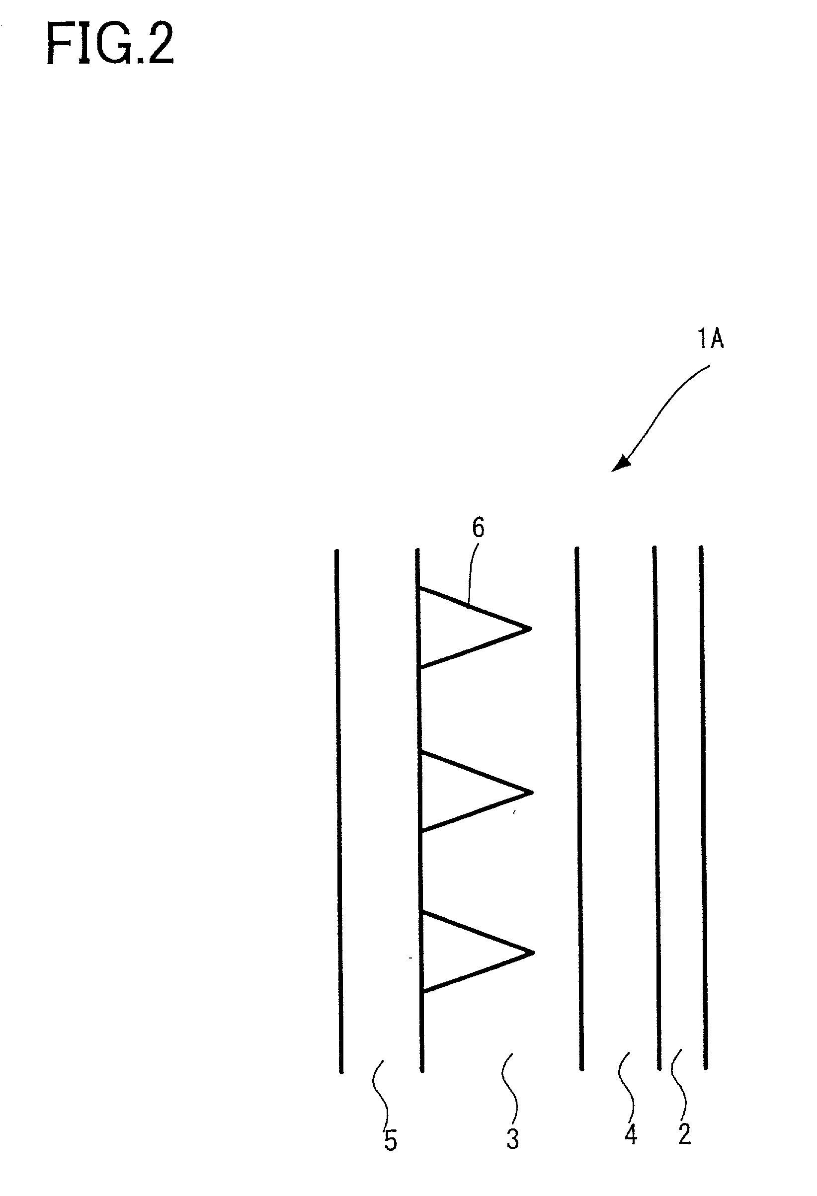
[0184] FIGS. 11 and 12 are views illustrating horizontal cross sections of the light diffusion sheets S1 and S2 according to the sixth and the seventh embodiments of the present invention. In each of these figures, on the right side of the illustration there is disposed an image light source while, on the left side of the illustration there is located the viewer.

sixth embodiment

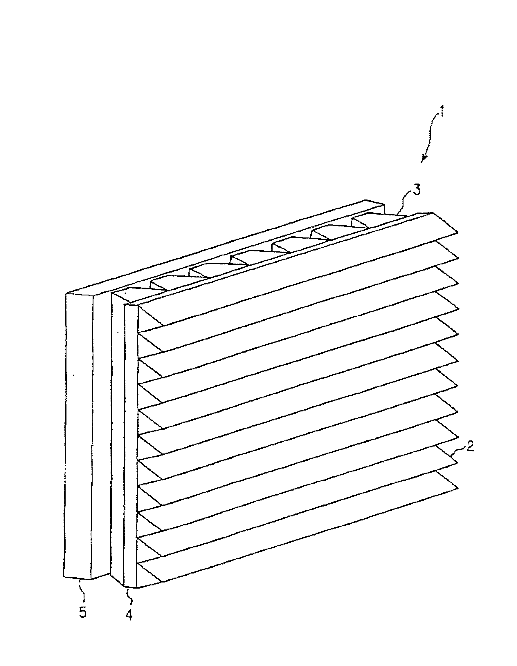
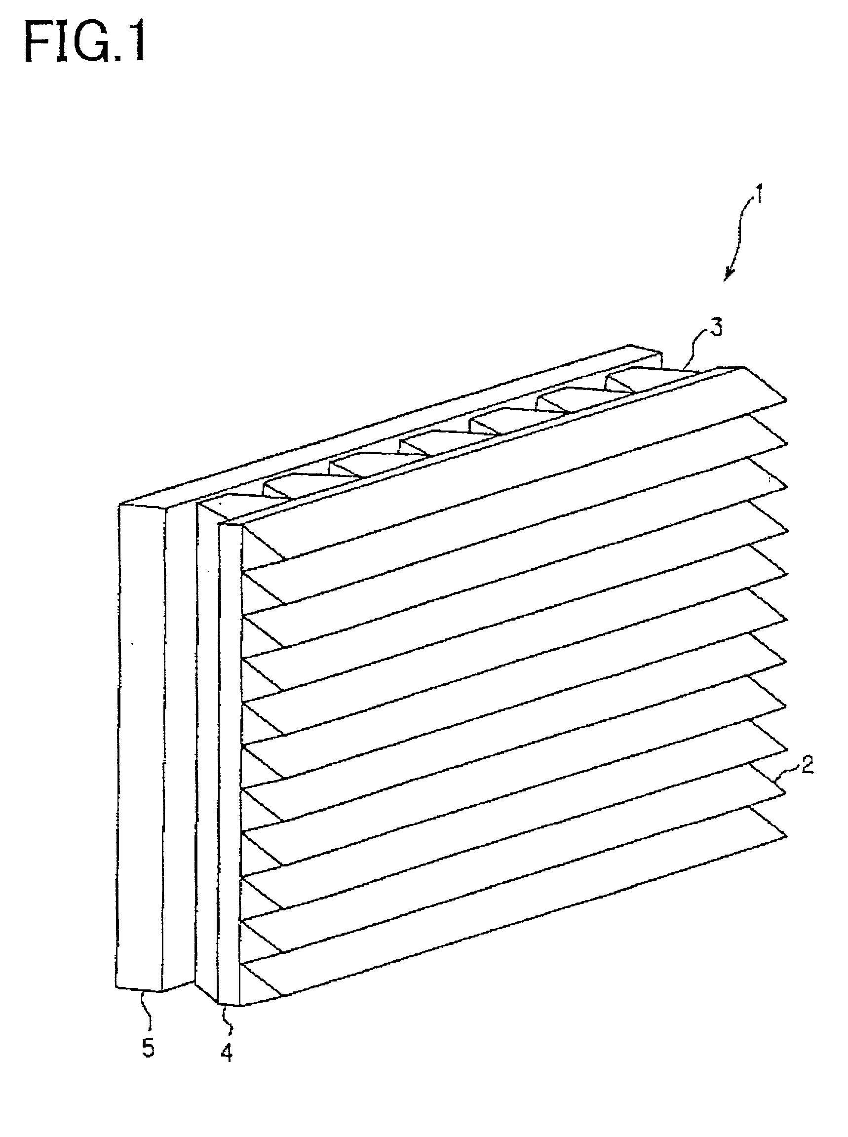
[0185] FIG. 11 illustrates the light diffusion sheet S1 according to the present invention. In this light diffusion sheet S1, from the viewer side toward the image light source, there are sequentially disposed a diffusion agent mixed sheet 101, unit lenses 102, and a base sheet 103 in the way they are bonded together. The unit lens 102 is formed using a material having a high refractive index N1. Further, in a portion that is defined between two adjacent of the unit lenses 102 and 102 and the cross sectional configuration of that is triangle (hereinafter referred to as "the between-lens portion 107"), there is embedded a material that has been prepared by adding the light absorption particles 105 into a transparent material having a refractive index N2 lower than the N1 (hereinafter referred to as "the transparent low refractive index material 106").

[0186] In this embodiment, the ratio between the refractive index N1of the high refractive index portion 102 and the refractive index N...


PUM


Abstract

Provided is a light diffusion sheet capable of preventing the reflection of an external light that has entered from the light emission surface and of obtaining a high gain, and a projection screen using the light diffusion sheet. In the light diffusion sheet or film, the light diffusion sheet or film having formed thereon a plurality of unit lenses one-dimensionally or two-dimensionally, the unit lens is substantially trapezoidal in cross section; the lower bottom of the trapezoid is made to be a light incidence portion and the upper bottom thereof is made to be a light emission portion; and the unit lens is formed using a material having a prescribed refractive index of N1; a portion, the cross section of that is triangular, and that is located between adjacent two of the unit lenses, is formed using a material having a refractive index N2 lower than the N1 and having added thereto light absorption particles; and when it is assumed that T represents the length of the upper bottom of the trapezoid; H represents the height of the upper bottom thereof; and theta represents the angle defined by the slant of the trapezoid with respect to a normal line to the light emission portion, the relationship holds true that is expressed as: <paragraph lvl="0"><in-line-formula>sin (90°-theta)>N2/N1 </in-line-formula><paragraph lvl="0"><in-line-formula>N1<1/sin 2theta</in-line-formula><paragraph lvl="0"><in-line-formula>0<H<T/(tan (2theta+10°)-tantheta) </in-line-formula>and the surface of the light incidence portion has performed thereon embossing processing.

Description

[0001] 1. Field of the Invention[0002] The present invention relates to a sheet or film for use for a projection screen, a projection screen, and a projection display device, and a light diffusion sheet or film and a projection screen using the light diffusion sheet or film, each of which is suitable for being viewed by having obliquely projected thereon an image from an image light source having a cell structure such as an LCD (Liquid Crystal Display Device), or a DMD (Digital Micro-mirror Device).[0003] 2. Description of the Related Art[0004] A rear-surface projection type projection display device using three CRTs of red, green, and blue as the image light source and using a transmission type projection screen as the projection screen is conventionally known. In general, the projection screen is constructed using a Fresnel lens sheet and a lenticular lens sheet, and it is the projection screen that is for the purpose of obtaining a diffusion surface having directionality by causi...

Claims


Application Information

Patent Timeline
Patent Type & Authority Applications(United States)
IPC IPC(8): G03B21/62
CPCG03B21/625
Inventor GOTO, MASAHIRO
Owner DAI NIPPON PRINTING CO LTD
Why Eureka
Try Eureka