
Rear projection screen

a projection screen and rear projection technology, applied in the field of rear projection screens, can solve the problems of inability to accurately transfer the lens shape, inability to meet the performance requirements above prior arts, and reduced mold li

Inactive Publication Date: 2003-04-29
MITSUBISHI RAYON CO LTD
View PDF32 Cites 50 Cited by
  • Summary
  • Abstract
  • Description
  • Claims
  • Application Information

AI Technical Summary

Benefits of technology

Further, the present invention has another object to provide a rear projection screen which has a sufficiently wide angle of visual field and is excellent in shock resistance and light transmission.

Problems solved by technology

However, when the number of pixels is increased to the level of XGA class or SXGA class or more or when an image is projected onto a relatively small screen of about 14 to 40 inches, the pitch of the lenticular lenses must be reduced to a very small value of about 0.1 mm or less to cancel the moire phenomenon because the pitch of the pixels constituting an image projected on the rear projection screen is very small, and thus there are problems that it is very difficult to manufacture a mold for such lenses, it is impossible to transfer the lens shape accurately, and the lifetime of the mold is reduced.
However, any of the above prior arts cannot satisfy all of the performance requirements (1) to (3).
However, in the case of the high pixel number such as XGA, SXGA class or higher case, the resolving power is reduced and thus a projected image of high resolution cannot be provided.
Sho-55-12980, occurrence of speckle is remarkable although a projected image of high resolution is obtained, and thus a high quality projection cannot be provided.
Hei-1-172801 and so on have such a problem that the strength of the transparent resin serving as a base member is lowered.
However, since such a light diffusion layer has a small thickness and contains a large amount of light diffuser, it is very difficult to manufacture the light diffusion layer, and also it is very difficult or cumbersome to handle the diffusion layer when it is carried or fabricated.
In addition, it is easily cracked due to an external shock even after it is set up.
When a light diffusing sheet is formed by an extrusion method using resin containing light diffuser, there are problems that the resin is liable to be accumulated at a portion (lip portion) through which the resin is jetted from a die, the light diffusing sheet comes into contact with the portion at which the resin is accumulated, thereby easily inducing appearance defect, and it is difficult to manufacture the light diffusing sheets stably for a long term.
However, when the rubber light diffuser is used, agglomeration of rubber particles is remarkable and thus dispersibility into the base resin is degraded.

Method used


Image

  • Rear projection screen
  • Rear projection screen
  • Rear projection screen

Examples


embodiment

of Sixth Aspect of the Invention

Next, an embodiment of the rear projection screen using a light diffusion sheet containing light diffusion coated particles according to the sixth aspect of the present invention.

The light diffusion sheet containing the light diffusion coated particles is obtained by adding the light diffusion coated particles to transparent resin. As shown in FIG. 17, the light diffusion coated particle 26 used in the light diffusion sheet is designed in such a core-shell structure that resin layer 28 is coated on the surface of silicone rubber spherical particle 27. The resin layer 28 is preferably formed of hard material, and is particularly preferably formed of polyorganosilsesquioxane resin.

In order to sufficiently exhibit the characteristic of the silicone rubber spherical particle 27, the ratio of the silicone rubber spherical particle 27 and the resin layer 28 is preferably set so that the volume ratio of the silicone rubber spherical particle 27 in the coated...

example 1

Formation of First Light Diffusion Layer

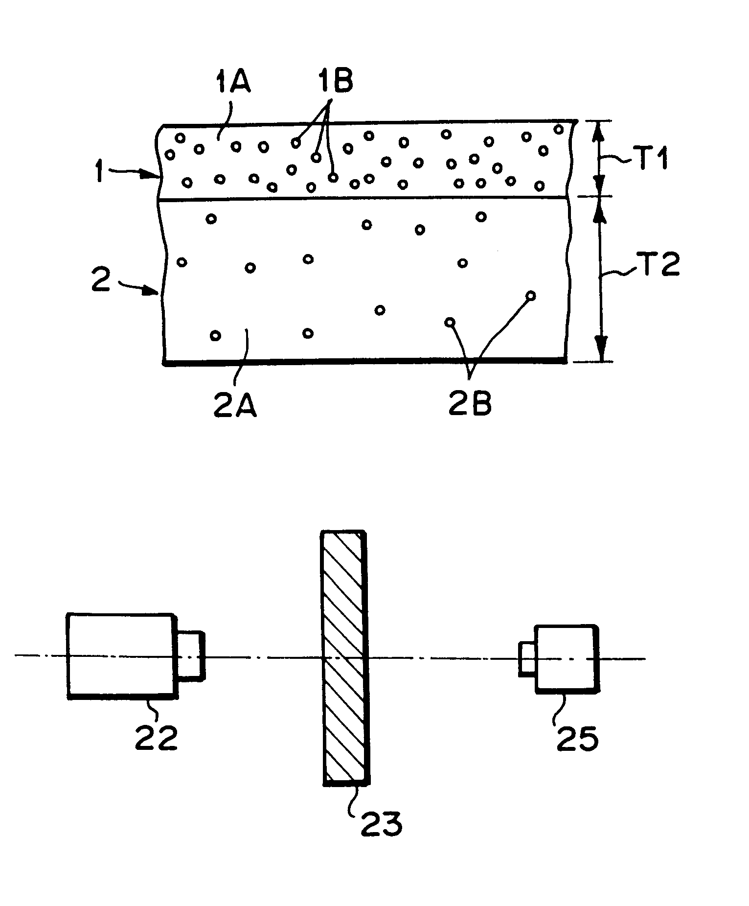
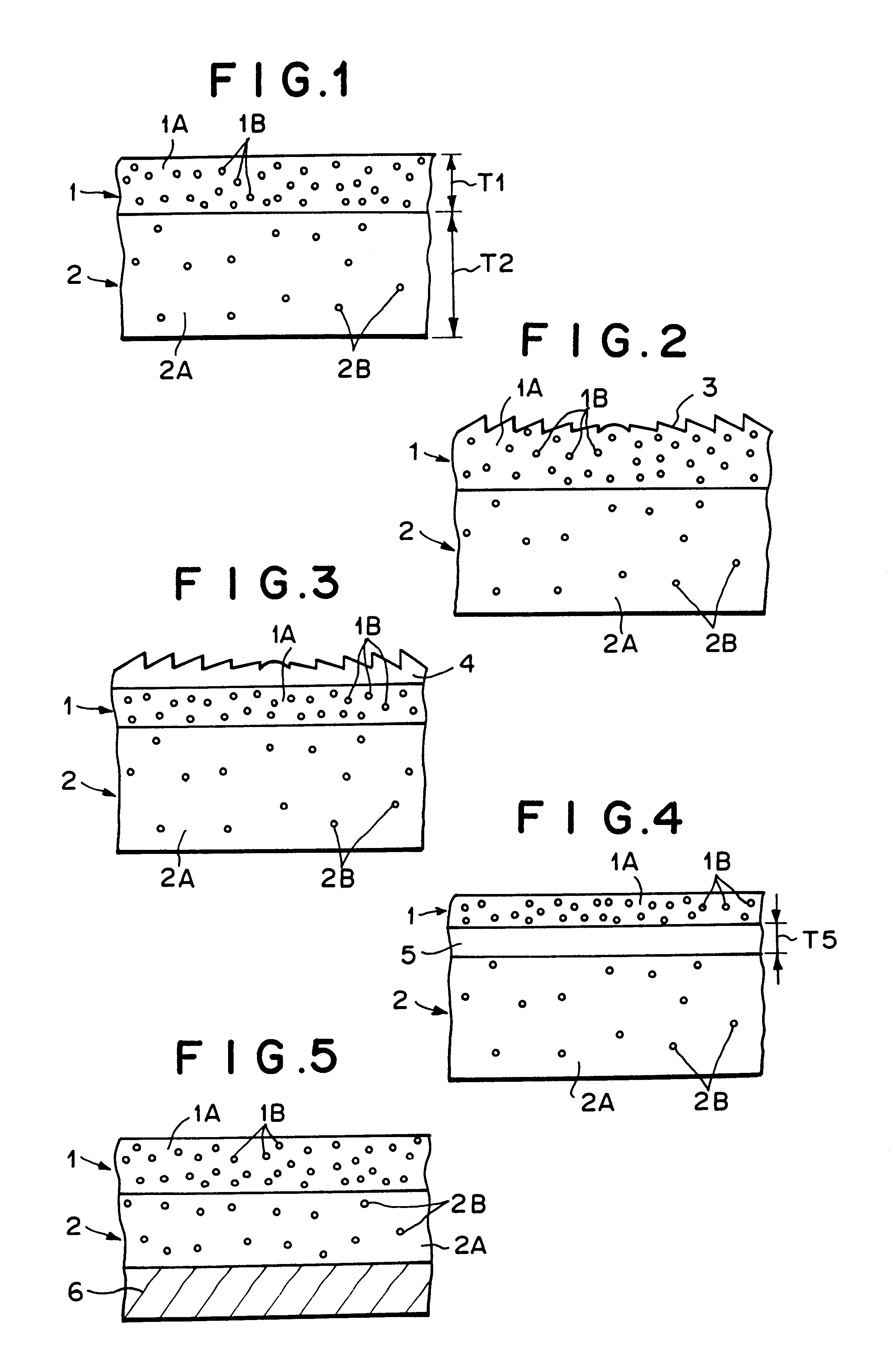
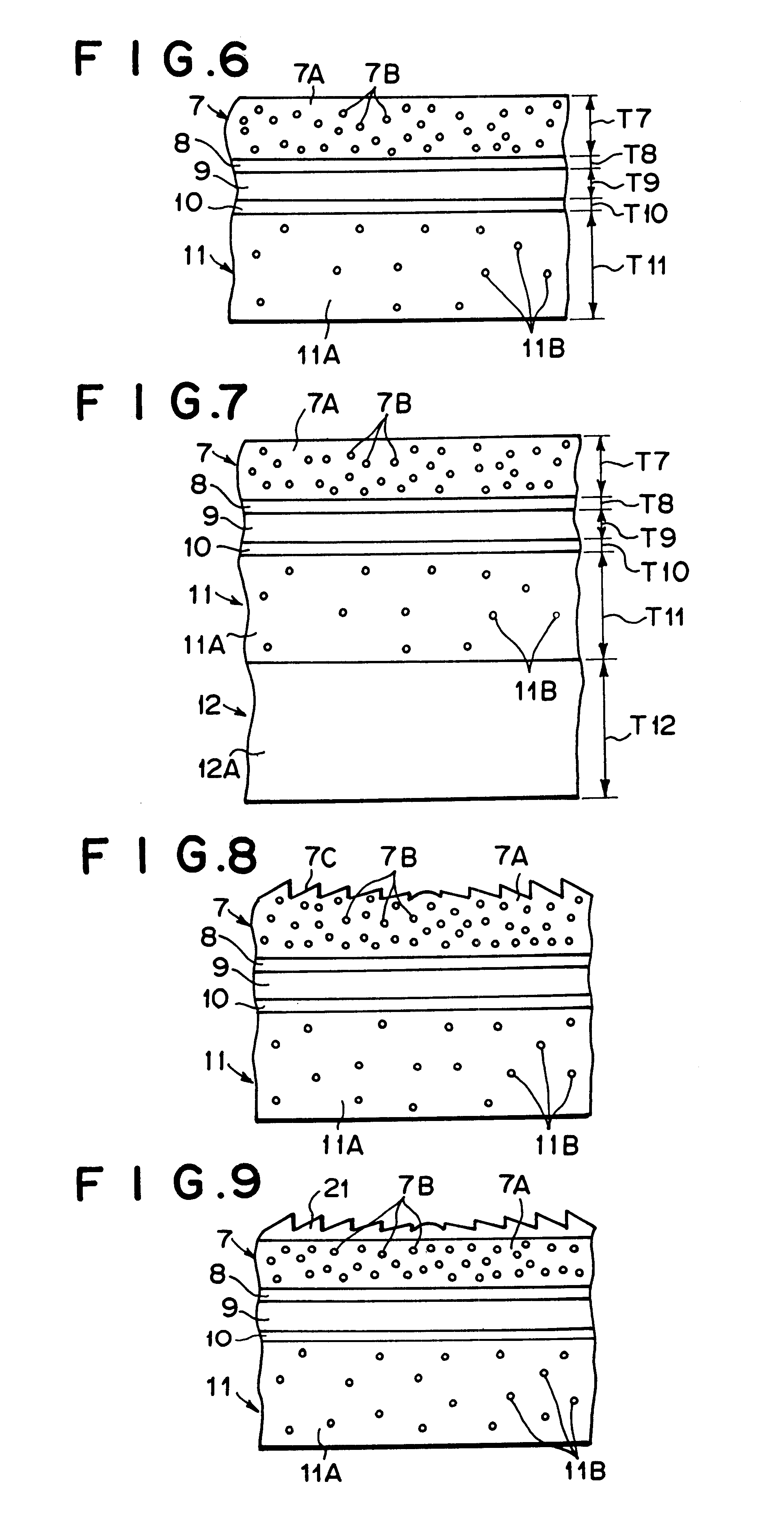
Acrylic resin pellets (ACRYPET RF-065, produced by Mitsubishi Rayon Co., Ltd.) were added to methyl ethyl ketone (MEK) solvent by 20 wt % and dissolved while stirred, thereby obtaining acrylic resin solution. Crosslinked styrene resin spherical fine particles having a weight average particle diameter of 6 .mu.m (SBX-6, produced by Sekisui Plastics Co., Ltd.: refractive index of 1.59) were added as the light diffuser 7B to the acrylic resin solution by 28.0 wt % with respect to acrylic resin, and stirred and mixed to uniformly disperse the particles in the acrylic resin solution. The acrylic resin solution containing the light diffuser was coated on a glass plate by using a bar coater so that the thickness was equal to 400 .mu.m under non-dried condition. Thereafter, it was heated and dried at 50.degree. C. for 10 minutes, and further at 100.degree. C. for 10 minutes to vaporize the solvent, and the dried result was exfoliated from the glass pl...

example 2

Formation of Second Light Diffusion Layer

Spherical glass beads having an weight average particle diameter of 10 .mu.m (EMB-10, produced by Toshiba Balotini Co., Ltd.: refractive index of 1.52) were added as the light diffuser 2B to methacrylic resin pellets (ACRYPET VH, produced by Mitsubishi Rayon Co., Ltd.) by 2.0 wt %, dispersed by using Henschel mixer, and then acrylic resin pellets contining the light diffuser were formed by using a double screw extruder of 30 mm .phi.. This pellet was sheeted by using a single screw extruder of 50 mm .phi. to obtain a second light diffusion layer 2 having a thickness of 2000 .mu.m. The light diffuser was uniformly dispersed in the second light diffusion layer 2. The optical characteristics of the second light diffusion layer thus obtained is shown in Table 1.

Lamination of First Light Diffusion Layer and Second Light Diffusion Layer

The second light diffusion layer thus obtained and the first light diffusion layer obtained in Example 1 were lami...


PUM


Abstract

A first light diffusion layer (1) and a second light diffusion layer (2) are provided. The first light diffusion layer (1) is formed by dispersing a first light diffuser (1B) comprising fine particles in a first base material (1A) formed of transparent resin by 20 to 50 wt %, the fine particles of the first light diffuser having a refractive index different from that of the first base material by 0.07 to 0.17 and having a weight average particle diameter of 1 to 12 mum, and the first light diffusion layer having a thickness of 50 to 200 mum. The second light diffusion layer (2) is formed by dispersing a second light diffuser (2B) comprising fine particles having a weight average particle diameter of 1 to 12 mum in a second base material (2A) formed of transparent resin by 0.1 to 10.0 wt %, and the second light diffusion layer having a thickness of 500 to 5000 mum and a Haze value of 50 to 85%.

Description

The present invention relates to an image display technique, and particularly to a rear projection screen which is suitably used as a screen for a projection television, a microfilm reader or the like. The rear projection screen of the present invention is suitably applicable to a rear projection screen onto which an optical image formed on a light valve (light source) having matrix-arranged picture element portions (that is, having such a structure that picture element portions are arranged in a matrix form) such as an LCD (liquid crystal device) projector or DMD (digital micromirror device) projector is projected.BACKGROUND TECHNIQUEFor rear projection type televisions, it has been hitherto required that projected images can be brightly viewed in a wide viewing angle range at the viewing side, and rear projection-screens having anisotropy in visual field which are designed to diffuse light broadly particularly in a horizontal direction and diffuse light properly in a vertical dire...

Claims


Application Information

Patent Timeline
Patent Type & Authority Patents(United States)
IPC IPC(8): G03B21/62
CPCG03B21/625G03B21/62G02B5/0242G02B5/3033G02B5/0278G02B3/08
Inventor MURAYAMA, YOSHIAKIHASEGAWA, HIDEKIFUJIKURA, NOBORUMATSUMOTO, MAKOTO
Owner MITSUBISHI RAYON CO LTD
Learn More