

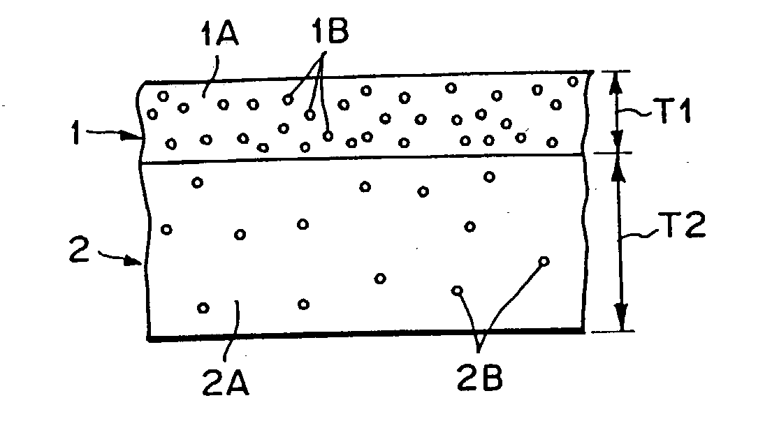
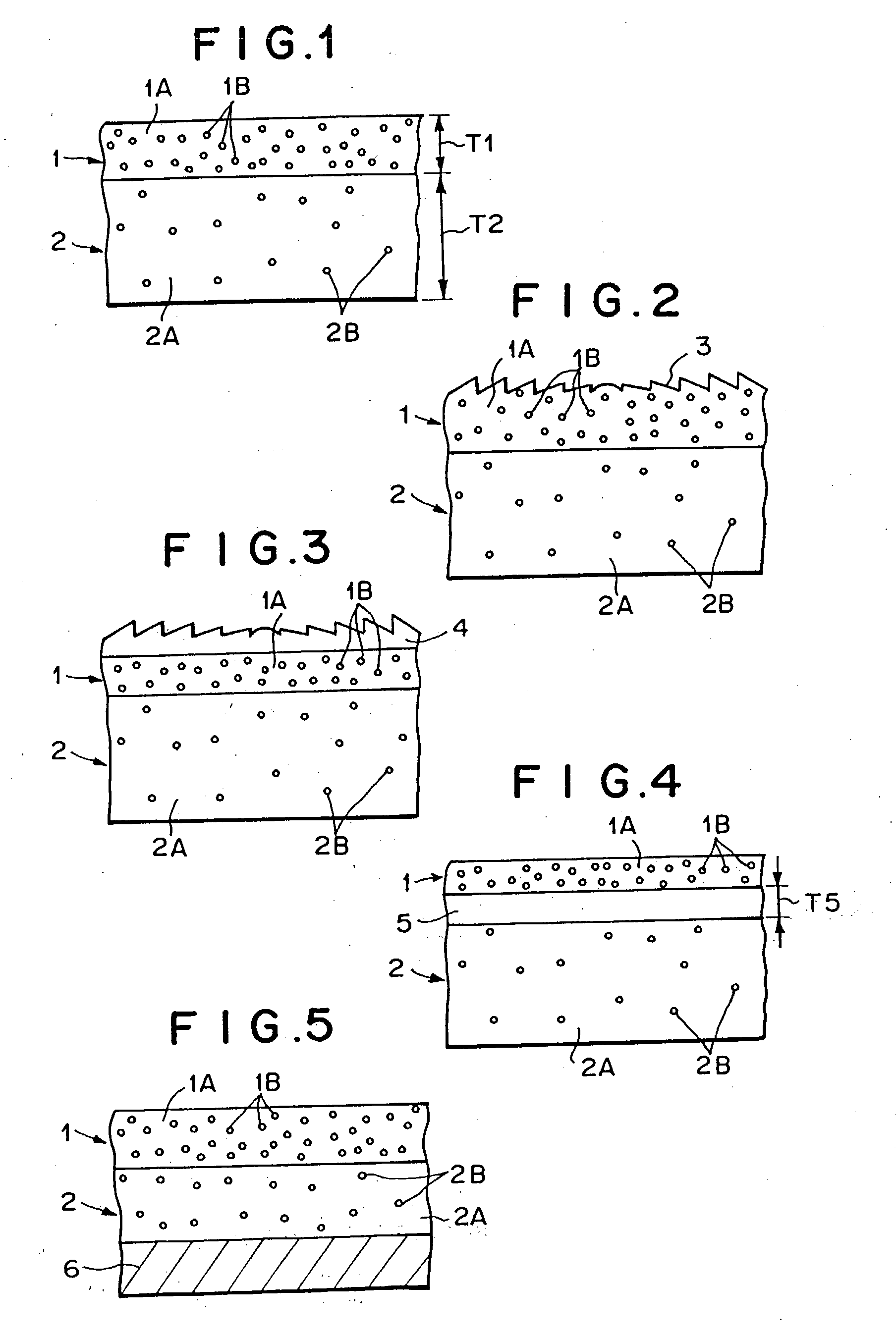
Rear projection screen
a projection screen and rear projection technology, applied in the field of rear projection screens, can solve the problems of inability to accurately transfer the lens shape, inability to meet the performance requirements above prior arts, and reduced mold li
- Summary
- Abstract
- Description
- Claims
- Application Information
AI Technical Summary
Benefits of technology
Problems solved by technology
Method used
Image

Examples
example 1
[0158] Formation of First Light Diffusion Layer
[0159] Acrylic resin pellets (ACRYPET RF-065, produced by Mitsubishi Rayon Co., Ltd.) were added to methyl ethyl ketone (MEK) solvent by 20 wt % and dissolved while stirred, thereby obtaining acrylic resin solution. Crosslinked styrene resin spherical fine particles having a weight average particle diameter of 6 .mu.m (SBX-6, produced by Sekisui Plastics Co., Ltd.: refractive index of 1.59) were added as the light diffuser 7B to the acrylic resin solution by 28.0 wt % with respect to acrylic resin, and stirred and mixed to uniformly disperse the particles in the acrylic resin solution. The acrylic resin solution containing the light diffuser was coated on a glass plate by using a bar coater so that the thickness was equal to 400 .mu.m under non-dried condition. Thereafter, it was heated and dried at 50.degree. C. for 10 minutes, and further at 100.degree. C. for 10 minutes to vaporize the solvent, and the dried result was exfoliated fro...
example 2
[0166] Formation of Second Light Diffusion Layer
[0167] Spherical glass beads having an weight average particle diameter of 10 .mu.m (EMB-10, produced by Toshiba Balotini Co., Ltd.: refractive index of 1.52) were added as the light diffuser 2B to methacrylic resin pellets (ACRYPET VH, produced by Mitsubishi Rayon Co., Ltd.) by 2.0 wt %, dispersed by using Henschel mixer, and then acrylic resin pellets contining the light diffuser were formed by using a double screw extruder of 30 mm .phi.. This pellet was sheeted by using a single screw extruder of 50 mm .phi. to obtain a second light diffusion layer 2 having a thickness of 2000 .mu.m. The light diffuser was uniformly dispersed in the second light diffusion layer 2. The optical characteristics of the second light diffusion layer thus obtained is shown in Table 1.
[0168] Lamination of First Light Diffusion Layer and Second Light Diffusion Layer
[0169] The second light diffusion layer thus obtained and the first light diffusion layer obt...
example 3
[0172] A rear projection screen was obtained in the same manner as Example 1 except that spherical silicone resin beads having a weight average particle diameter of 3 .mu.m (TOSPEARL 130 (TP130), produced by Toshiba Silicone Co., Ltd.: refractive index of 1.42) were added as the first light diffuser 1B of the first light diffusion layer 1 by 40 wt %, and the second light diffuser 2B of the second light diffusion layer 2 was added by 1.4 wt %.
[0173] The optical characteristics of the first light diffusion layer 1 and the second light diffusion layer 2 are shown in Table 1. The measurement results of the characteristics of the rear projection screen is shown in Table 2. In the rear projection screen thus obtained, no speckle occurred while the resolution (MTF) was high (30%), and the .alpha.-value was equal to 36.0 degrees, which indicated that a sufficient angle of visual field was obtained. Accordingly, there could be obtained an image having uniform brightness over the overall imag...
PUM
 Abstract
Description
Claims
Application Information