Adjustable tether assembly for fiber optic distribution cable

a technology of fiber optic distribution cable and tether assembly, which is applied in the direction of optics, fibre mechanical structures, instruments, etc., can solve the problems of difficult to identify a particular optical fiber of the distribution cable, difficult to reconfigure optical connections within the splice closure, and often requires the assistance of highly skilled field technicians at significant cost and under field working conditions

Inactive Publication Date: 2007-06-05
CORNING OPTICAL COMM LLC
View PDF34 Cites 92 Cited by
  • Summary
  • Abstract
  • Description
  • Claims
  • Application Information

AI Technical Summary

Benefits of technology

[0009]To achieve the foregoing and other objects, and in accordance with the purposes of the invention as embodied and broadly described herein, the present invention provides various embodiments of a fiber optic distribution cable having an adjustable tap point that includes a relatively short length of cable, referred to herein as a “tether”, that permits at least one connector port to be accurately positioned at a desired location in a fiber optic communications network. In further embodiments, the present invention provides a fiber optic distribution cable assembly having at least one, and preferably a plurality of, predetermined mid-span access locations that serve as “tether attach points,” and at least one connector port that is attached to a respective mid-span access location by a tether. The connector port is slidable along the length of the distribution cable, or may be separated from and positioned away from the distribution cable in order to mitigate span length measurement differences encountered during installation of the distribution cable and thereby provide a distribution or termination point at a desired location within a fiber optic communications network. The connector port and tether are manufactured in the factory and spliced or otherwise optically connected in the field to a previously installed fiber optic distribution cable. Alternatively, a fiber optic distribution cable assembly including a tether and at least one connector port is manufactured in the factory (i.e., factory-prepared) for a pre-engineered fiber optic communications network and wound onto a cable reel for deployment in the field. The tether provides a relatively short length of cable at each mid-span access location to allow a distribution or termination point to be positioned at a desired location, thereby eliminating the need for absolute accuracy in the engineering of the fiber optic network, the manufacture of the distribution cable assembly and the deployment of the distribution cable assembly.
[0013]In yet another exemplary embodiment, the present invention provides a method of mitigating cable length errors in a pre-engineered fiber optic communications network comprising a fiber optic distribution cable assembly having at least one mid-span access location. The method comprises optically connecting preterminated optical fibers of the distribution cable to one or more optical fibers of a tether cable attached to the distribution cable at the mid-span access location, and positioning at least one connector port at a downstream end of the tether at a desired location to compensate for cable length errors encountered in the pre-engineering of the network, or the manufacture or deployment of the distribution cable.

Problems solved by technology

In particular, it is often difficult to identify a particular optical fiber of the distribution cable to be optically connected with an optical fiber of a drop cable.
In either case, the process of configuring the mid-span access location is not only time consuming, but frequently must be accomplished by a highly skilled field technician at significant cost and under field working conditions that are less than ideal.
In situations in which a mid-span access location is enclosed within a conventional splice closure, reconfiguring optical connections within the splice closure is especially difficult, based in part on the relatively inaccessible location of the closure, the limited workspace available within the closure, and the inability to readily remove the closure from the distribution cable.
Further, once the spliced optical connections are made, it is labor intensive, and therefore relatively costly, to reconfigure the optical connections or to add additional optical connections.
If extra length of distribution cable is used, the incorrect placement of even one mid-span access location will have a compounding effect on the position of each downstream mid-span access location.
As a result, all downstream mid-span access locations will be out of position and the length of distribution cable will come up short at the end of the cable run.
Obviously, measuring the absolute distances between mid-span access locations and building a distribution cable assembly with accurate distances between mid-span access locations is a difficult undertaking.
Furthermore, any error in the manufacturing process may result in the entire distribution cable assembly being unusable, and therefore scrapped.
The obvious drawbacks with such a distribution cable assembly are the cost associated with the excess lengths of the cable and the associated need to store the cable slack in an aesthetic and practical manner.
In addition to the difficulties associated with manufacturing a distribution cable assembly having the tap points in the pre-engineered locations, there are also problems encountered with using conventional components to optically connect the optical fibers of the distribution cable with optical fibers of a branch cable or drop cable at the mid-span access locations.
Distribution cables provided with conventional enclosures tend to be large in size and inflexible, and thus, unable to satisfy common deployment constraints, such as being wound onto a reel, deployed through conduits having a relatively small inner diameter or significant bends, or deployed through conventional aerial lashing equipment, such as sheaves and rollers.
Furthermore, such enclosures are often structurally complex and difficult to install.
Accordingly, there is a specific and unresolved need for a factory-prepared, fiber optic distribution cable having an adjustable tap point that mitigates the difference between the pre-engineered span length distance and the actual span length distance following installation of the distribution cable.
In addition, there is a specific and unresolved need for a factory-prepared fiber optic distribution cable that does not require a highly skilled field technician or extensive field labor to interconnect optical fibers of the distribution cable with optical fibers of a branch cable or drop cable.

Method used


Image

  • Adjustable tether assembly for fiber optic distribution cable
  • Adjustable tether assembly for fiber optic distribution cable
  • Adjustable tether assembly for fiber optic distribution cable

Examples


Embodiment Construction

[0024]The present invention will now be described more fully hereinafter with reference to the accompanying drawings in which exemplary embodiments of the invention are shown. However, the invention may be embodied in many different forms and should not be construed as limited to the embodiments set forth herein. These exemplary embodiments are provided so that this disclosure will be both thorough and complete, and will fully convey the scope of the invention and enable one of ordinary skill in the art to make, use and practice the invention. Like reference numbers refer to like elements throughout the various drawings.

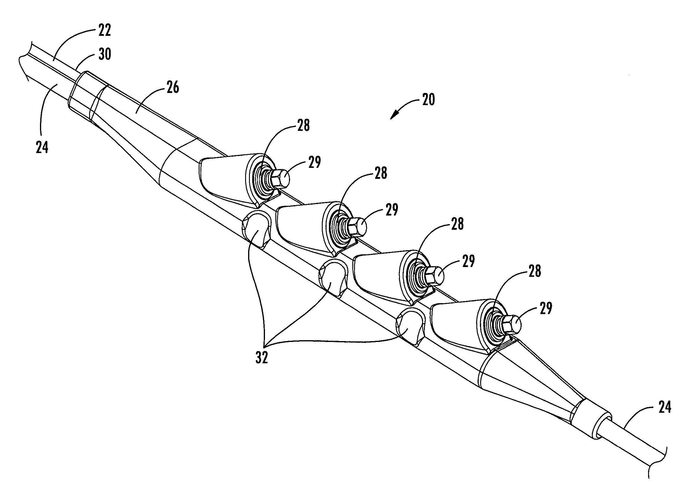
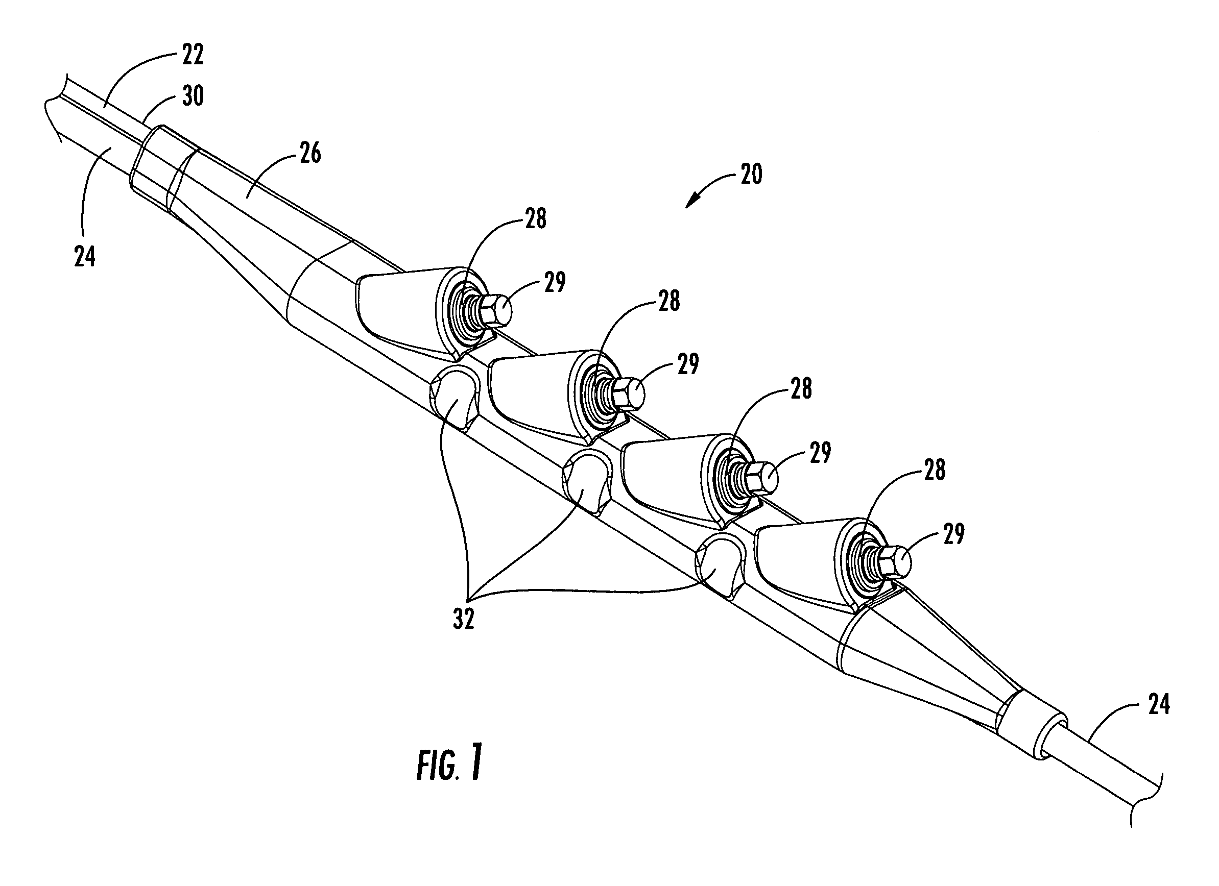
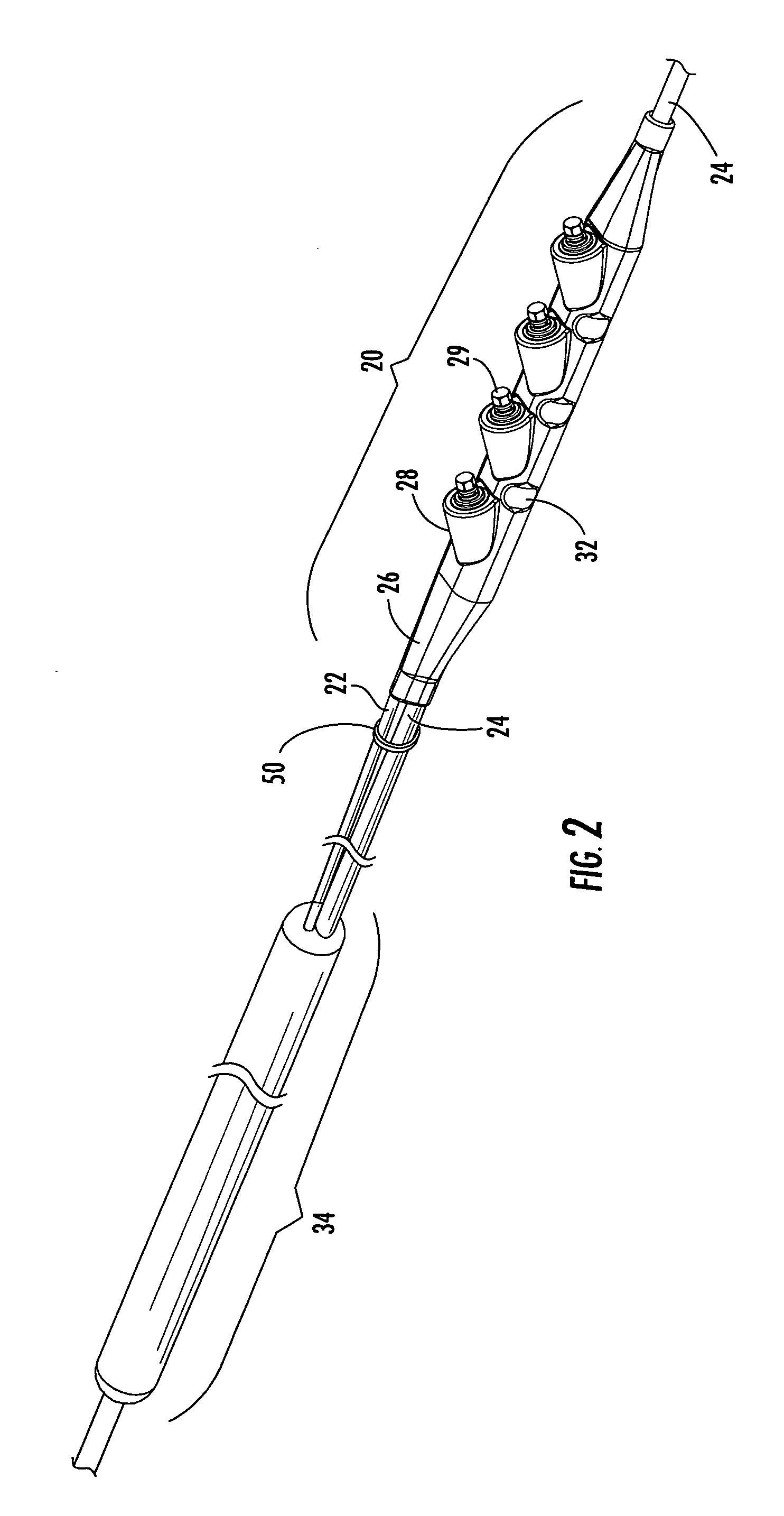
[0025]In one method of use, the tether assembly of the present invention mitigates span length measurement issues that result from the improper location of a mid-span access location on a fiber optic distribution cable due to differences between a pre-engineered span length distance and the actual span length distance following installation of a distribution cable. I...


PUM


Abstract

An adjustable tether assembly for a fiber optic distribution cable includes a tether cable and an overmolded housing secured at the end of the tether cable having at least one connector port. The tether assembly is attached to the distribution cable such that the position of the connector port is adjustable along the length of the distribution cable for mitigating differences between the pre-engineered span length distance and the actual span length distance following installation of the distribution cable. A method for mitigating a span length measurement difference in a pre-engineered fiber optic communications network is provided that includes optically connecting an adjustable tether assembly at a mid-span access location of a fiber optic distribution cable and positioning a housing secured at the free end of a tether cable having at least one connector port at a desired location in the network to compensate for the span length measurement difference.

Description

BACKGROUND OF THE INVENTION[0001]1. Field of the Invention[0002]The present invention relates generally to an interconnection, or “tap,” point in a fiber optic communications network. More specifically, the invention is a fiber optic distribution cable having an adjustable tap point comprising at least one connector port attached by a tether to a mid-span access location of the fiber optic distribution cable, wherein the tether provides a length of slack cable to permit the connector port to be positioned at a desired location in the fiber optic communications network.[0003]2. Description of the Related Art[0004]Optical fiber is increasingly being used for a variety of broadband communications including voice, video and data transmissions. As a result of the increasing demand for broadband communications, fiber optic networks typically include a large number of mid-span access locations at which one or more optical fibers are terminated from a distribution cable and interconnected w...

Claims


Application Information

Patent Timeline
Patent Type & Authority Patents(United States)
IPC IPC(8): G02B6/44
CPCG02B6/4441G02B6/4472
Inventor ELKINS, II, ROBERT B.KNECHT, DENNIS M.LUTHER, JAMES P.NIELSEN, LARS K.THEUERKORN, THOMAS
Owner CORNING OPTICAL COMM LLC
Why Eureka
Try Eureka