Shoulder prosthesis with anatomic reattachment features
What is AI technical title?
AI technical title is built by Patsnap AI team. It summarizes the technical point description of the patent document.
a shoulder prosthesis and anatomic reattachment technology, applied in the field of shoulder prosthesis with anatomic reattachment, can solve the problems of unsatisfactory final configuration, inability to address the simultaneous and inability to meet the need for up-and-down and/or rotational stabilization
Inactive Publication Date: 2007-06-12
MEDIDEA
View PDF55 Cites 24 Cited by
Summary
Abstract
Description
Claims
Application Information
AI Technical Summary
This helps you quickly interpret patents by identifying the three key elements:
Problems solved by technology
Method used
Benefits of technology
Benefits of technology
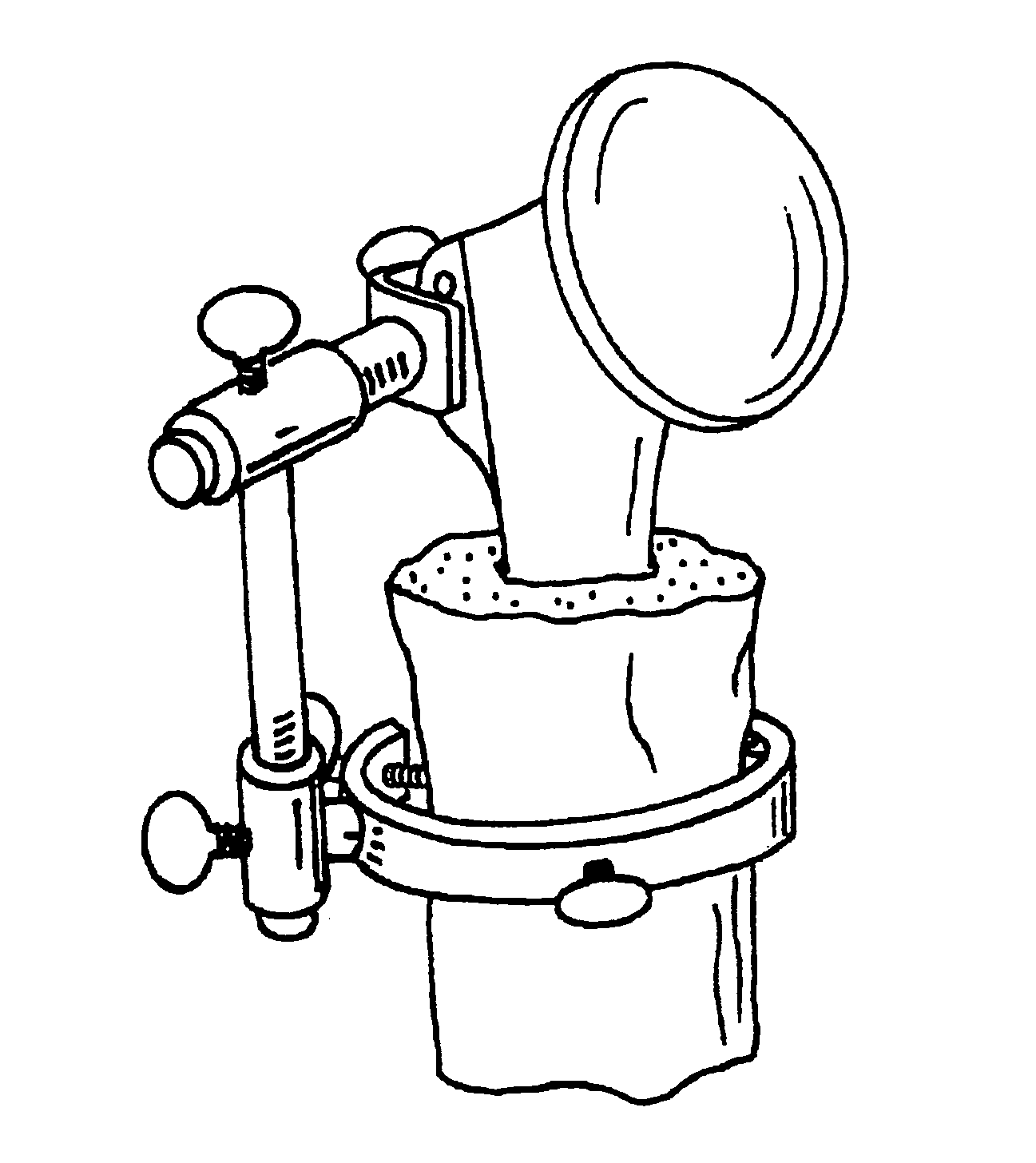
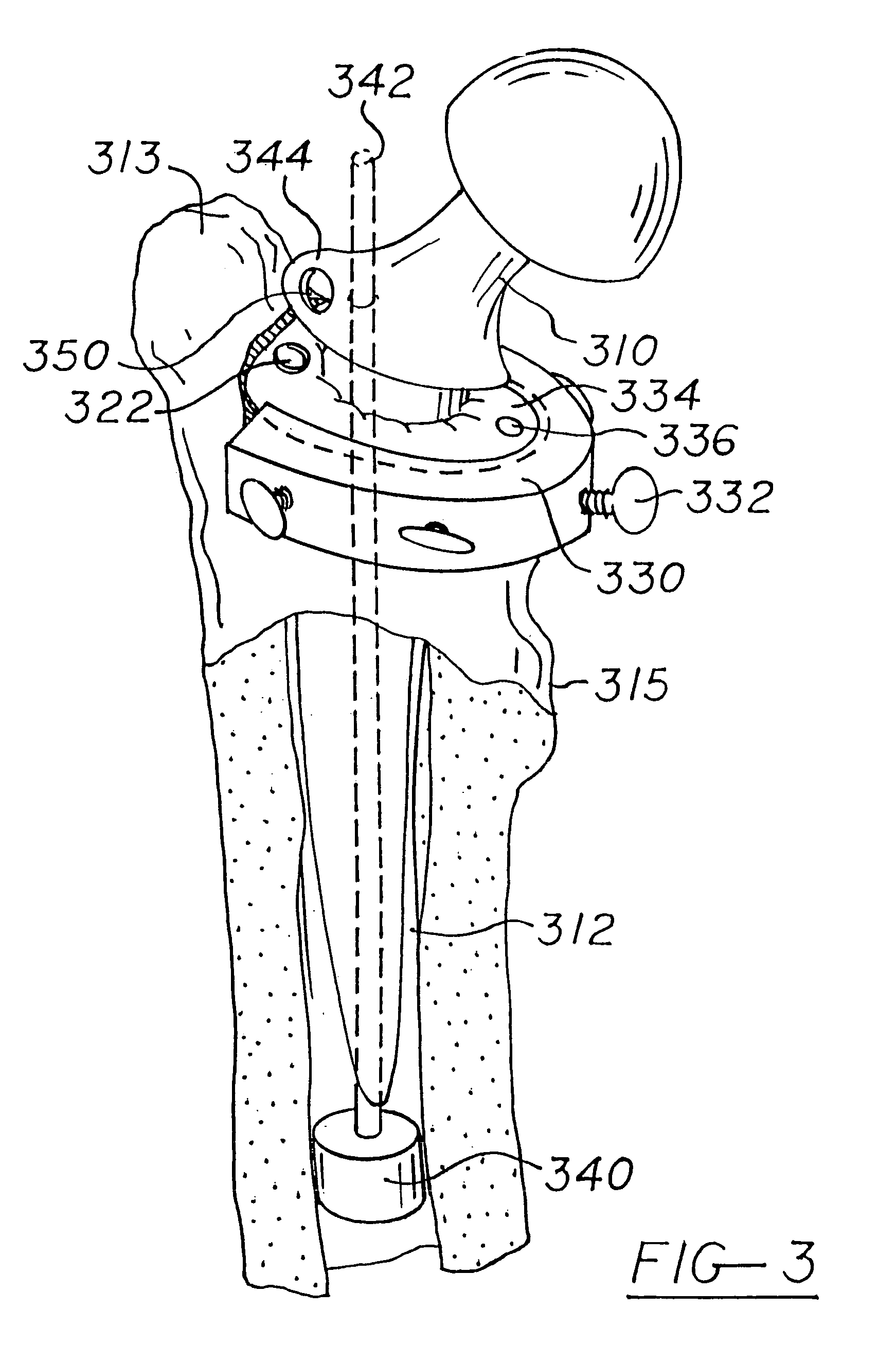
[0006]The present invention resides in apparatus and methods for maintaining the proper positioning of a prosthetic implant having proximal and distal ends within a prepared bone cavity during cement injection and curing. In contrast to prior-art systems the invention provides first stabilization means, implantable within the bone cavity, for minimizing lateral movement of the distal end of the implant, and second stabilization means, physically separate from the means for minimizing lateral movement of the distal end of the implant, for minimizing both the lateral movement of the proximal end of the implant and the rotational movement of the implant overall. In the preferred embodiment, the second stabilization means includes an apertured cap removably securable to the end of a bone having the prepared cavity through which the implant is inserted and held in place. This cap, which may either be entirely rigid or include a pliable membrane in the vicinity of the aperture, preferably further includes a first port associated with cement injection and a second port associated with cement over-pressurization. In an alternative embodiment, the second stabilization means includes a manually operated mechanism enabling the implant to be temporarily yet rigidly secured thereto in accordance with a desired orientation, preferably affording adjustments along multiple degrees of freedom prior to the rigid securement thereof.
Problems solved by technology
Foremost among them arises from the unpredictable process of ensuring that, although the prosthesis may have been ideally placed prior to cementation, once the cement is applied, orientation may shift, resulting in a final configuration which is less than optimal.
Although this technique may assist in maintaining a side-to-side orientation prior to cementation, it does not address the simultaneous need for up-and-down and / or rotational stabilization.
Additionally, as with current techniques, cement is applied to the host prior to the introduction of the final implant, leaving open the possibility that the final implant may be held in a position different from that associated with the trial, and may therefore result in an unacceptable misplacement as the cement cures.
Due to their requirement for a highly specialized final prosthetic element, such systems are incompatible with currently available implant devices, and therefore raise costs while reducing the options of the practitioner.
In addition, they do not adequately address the need for simultaneously stabilizing multiple degrees of freedom prior and during cementation.
As a further disadvantage, the systems which use the prosthesis as the cement injector tend to use the cement as a grout between the outer surface of the implant and the inner surface of the receiving cavity.
Method used
Image
Click on the blue label to locate the original text in one second.
Reading with bidirectional positioning of images and text.
Examples
Embodiment Construction
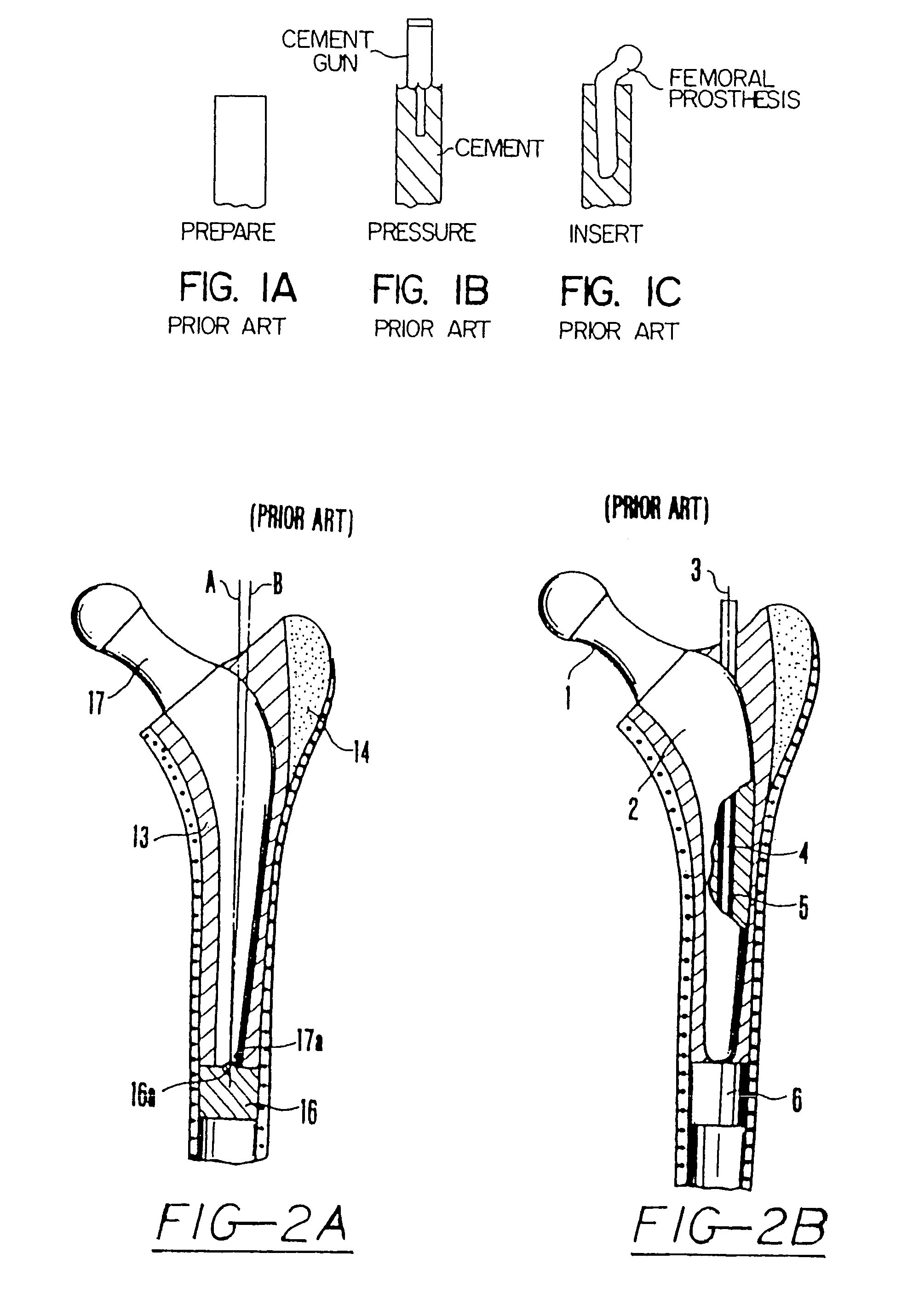
[0017]FIG. 1 of U.S. Pat. No. 5,340,362 shows an existing, prior-art procedure for inserting and cementing a prosthesis into a bone cavity, and this figure has been reproduced herein. In accordance with this technique, the canal is reamed or broached as shown in FIG. 1A, and a trial is typically inserted thereinto to ensure that the final prosthetic component will be properly received. After this trialing, cement is injected into the excavated area as shown in FIG. 1B, and the prosthesis is inserted as shown in FIG. 1C, and left in position while the cement hardens. As discussed in the background of the instant invention, the technique just described is deficient in that, although the prosthesis may be optimally oriented during the trial procedure, the position of the actual implant may shift upon insertion into the cemented host or thereafter, resulting in a misaligned final fixation.
[0018]Various improvements also exist in the prior art to minimize such adjustment problems. At the...
PUM
Abstract
Apparatus and methods are disposed for maintaining the proper positioning of a prosthetic implant having proximal and distal ends within a prepared bone cavity during cement injection and curing. First stabilization means, implantable within the bone cavity, minimize lateral movement of the distal end of the implant, while second stabilization means, physically separate from the means for minimizing lateral movement of the distal end of the implant, minimize both the lateral movement of the proximal end of the implant and the rotational movement of the implant overall. In the preferred embodiment, the second stabilization means includes an apertured cap removably securable to the end of a bone having the prepared cavity through which the implant is inserted and held in place. This cap, which may either be entirely rigid or include a pliable membrane in the vicinity of the aperture, preferably further includes a first port associated with cement injection and a second port associated with cement over-pressurization. In an alternative embodiment, the second stabilization means includes a manually operated mechanism enabling the implant to be temporarily yet rigidly secured thereto in accordance with a desired orientation, preferably affording adjustments along multiple degrees of freedom prior to the rigid securement thereof.
Description
REFERENCE TO RELATED APPLICATIONS[0001]This is a continuation application of U.S. patent application Ser. No. 10 / 091,846, filed Mar. 6, 2002, now U.S. Pat. No. 6,821,300 which is a continuation of U.S. patent application Ser. No. 09 / 396,576, filed Sep. 15, 1999, now U.S. Pat. No. 6,379,391, which is a continuation of U.S. patent application Ser. No. 09 / 029,457, filed Mar. 5, 1998, now U.S. Pat. No. 6,267,785, which is a U.S. national phase application of Patent Cooperation Treaty application Ser. No. US97 / 01754, filed Jan. 31, 1997, which claims priority of U.S. patent application Ser. No. 08 / 595,277, filed Feb. 2, 1996, now abandoned. The entire contents of each application is incorporated herein by reference.FIELD OF THE INVENTION[0002]This invention relates generally to arthroplasty and, more particularly to devices and techniques for positioning a prosthesis prior to fixation through the injection of a bonding agent.BACKGROUND OF THE INVENTION[0003]In current joint repair situat...
Claims
Application Information
Patent Timeline
Application Date:The date an application was filed.
Publication Date:The date a patent or application was officially published.
First Publication Date:The earliest publication date of a patent with the same application number.
Issue Date:Publication date of the patent grant document.
PCT Entry Date:The Entry date of PCT National Phase.
Estimated Expiry Date:The statutory expiry date of a patent right according to the Patent Law, and it is the longest term of protection that the patent right can achieve without the termination of the patent right due to other reasons(Term extension factor has been taken into account ).
Invalid Date:Actual expiry date is based on effective date or publication date of legal transaction data of invalid patent.

