Electrostatic motor utilizing static electricity as a drive force

a technology of electric motor and static electricity, which is applied in the direction of electrostatic motor, electrostatic generator/motor, electrical apparatus, etc., can solve the problems of difficult compactness, extremely difficult alignment and assembly of stator and slider film electrodes, etc., and achieves the effect of more powerful electrostatic motor and easy assembly

Inactive Publication Date: 2007-06-12
FANUC LTD
View PDF14 Cites 11 Cited by
  • Summary
  • Abstract
  • Description
  • Claims
  • Application Information

AI Technical Summary

Benefits of technology

[0022]An object of the present invention is to solve the above assembly problems and provide an easy-to-assemble electrostatic motor.
[0028]By stacking a plurality of electrostatic motor units each formed by stacking, with a gap, the stator film electrode provided with the step and the slider film electrode provided with the step, it is possible to obtain a more powerful electrostatic motor.
[0029]In the present invention, since parts of the stator and slider film electrodes are formed with thick parts forming step differences, even if the film electrodes are subjected to a slight force, they will not change in position and orientation. Further, at the time of assembly, there are fewer members to be aligned, so assembly becomes easier.

Problems solved by technology

A conventional electric motor using electromagnetic force requires a magnetic coil, permanent magnets, or other members for generating magnetic force and is difficult to make compact.
This makes it extremely difficult to align and assemble the stator and slider film electrodes 1, 2 and the spacer members 10 all at once.

Method used


Image

  • Electrostatic motor utilizing static electricity as a drive force
  • Electrostatic motor utilizing static electricity as a drive force
  • Electrostatic motor utilizing static electricity as a drive force

Examples


first embodiment

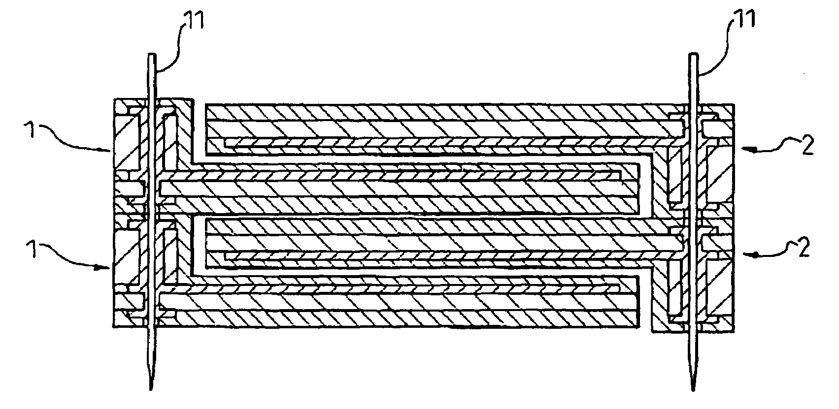
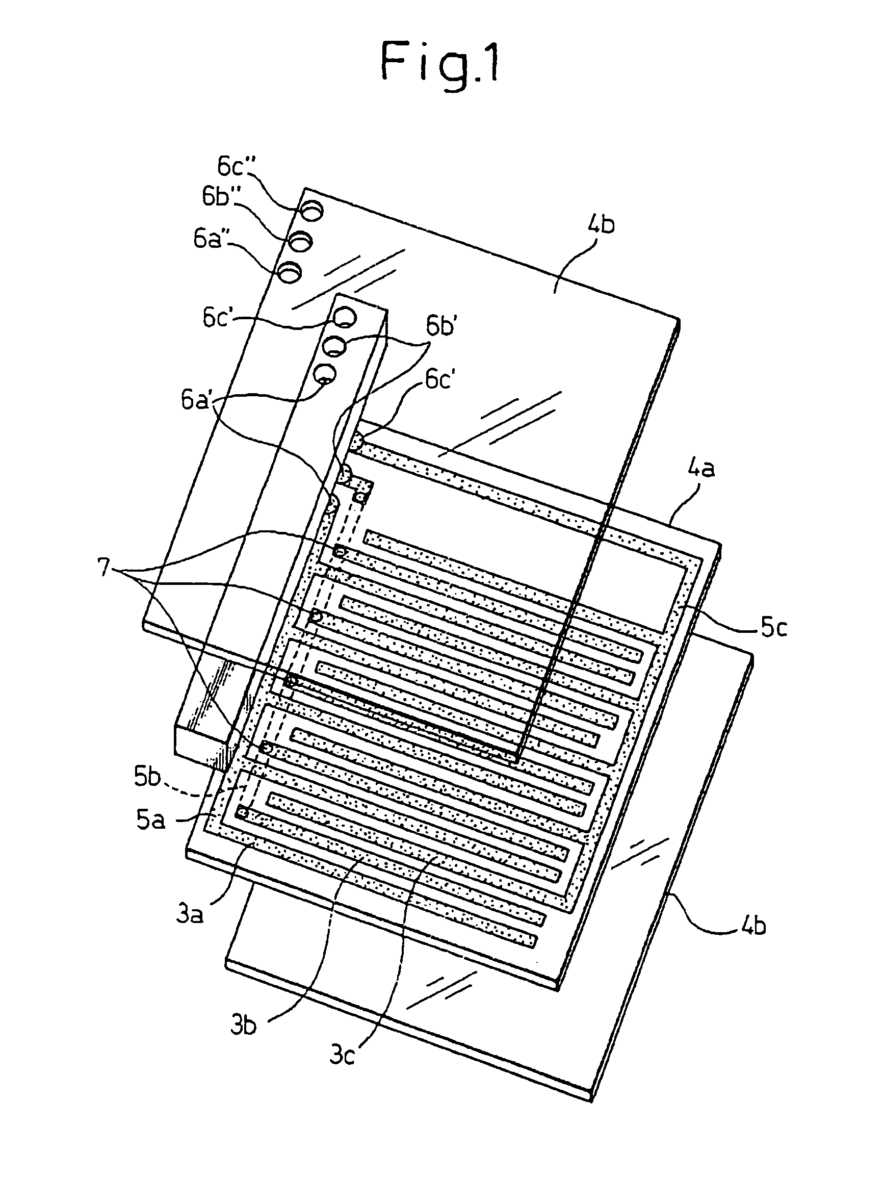
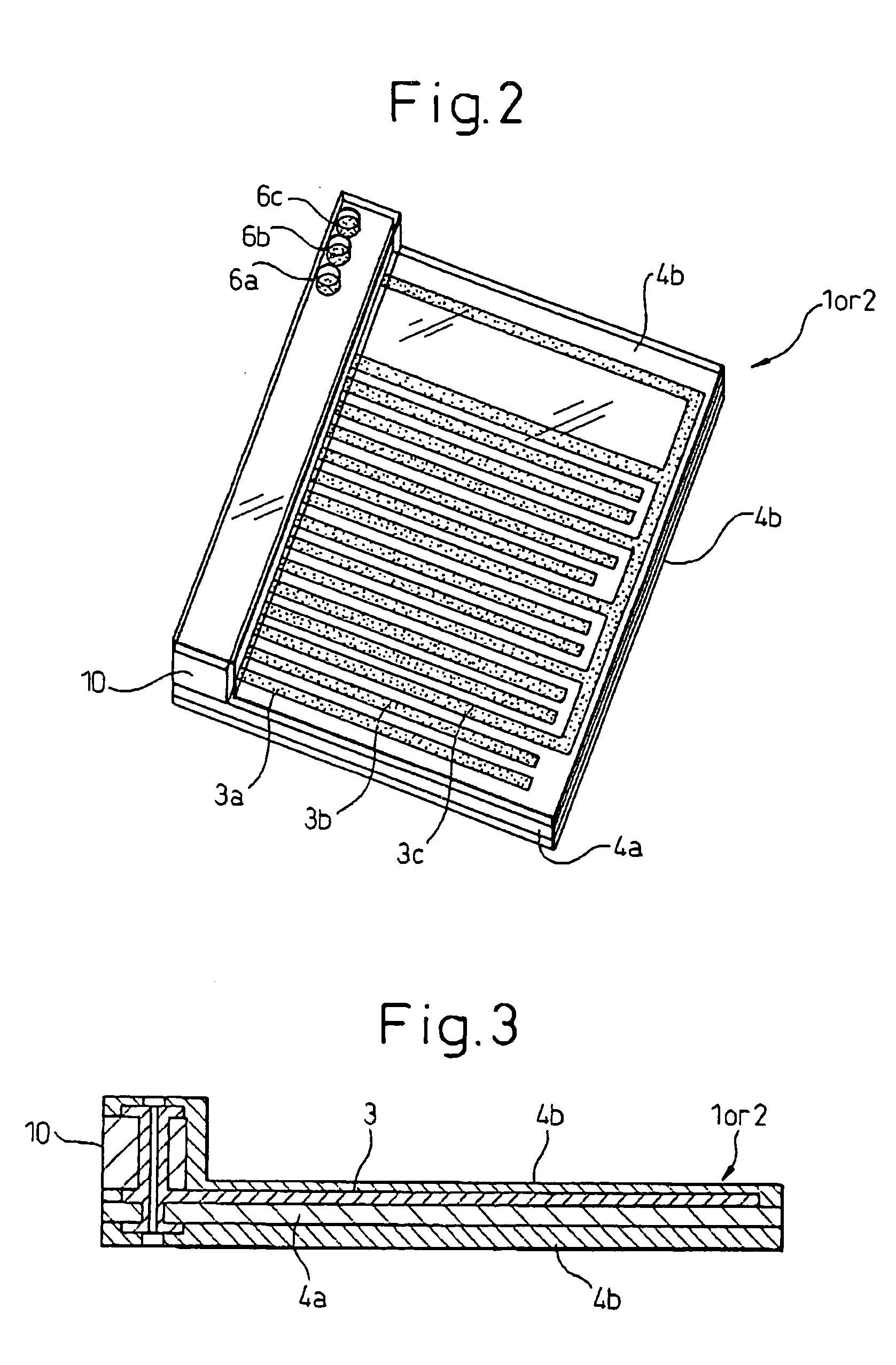
[0060]FIG. 1 to FIG. 4 are views for explaining a process of assembly of an electrostatic motor using spacer member-equipped film electrodes according to the present invention. The electrostatic motor of the present invention, in the same way as the past, can be constructed as a linear electrostatic motor or a rotary electrostatic motor such as shown in FIG. 20 and FIG. 21, but in this embodiment, the example of the electrostatic motor constructed as a linear electrostatic motor will be explained. Elements corresponding to elements of the prior art shown in FIG. 20 to FIG. 28 are assigned the same reference numerals.

[0061]Note that in FIGS. 1, 2, 5, 6, 9, 10, 14, 15, 16, 17, 12 and 19, the cover films 4b are illustrated as being transparent members for convenience in illustration, but the cover films 4b do not have to be transparent members.

[0062]The steps until forming on the base film 4a the electrode elements 3a to 3c and the patterns of the power feed paths 5a to 5c to be connec...

second embodiment

[0070]As shown in FIG. 5, one end of the base film 4a′ is formed with a step projecting out compared with the other parts. Further, the side of the base film 4a′ where the electrode elements 3a to 3c are provided, that is, the opposite side to the side where the step is formed, is a flat shape with no step. Further, the part where the step forming the spacer member 10′ is provided is provided with power feed paths 5a, 5b for feeding power to the electrode elements 3a, 3b. In the second embodiment, the flat surface on the side where the electrode elements 5a, 5b are provided is provided with the power feed path 5a for feeding power to the first electrode elements 3a, while the opposite surface is provided with the power feed path 5b for feeding power to the second electrode elements 3b and through hole conductive parts 7 are used to electrically connect to second electrode elements 3b arranged at the opposite surface. The power feed paths 5c to the third electrode elements 3c are pro...

fourth embodiment

[0077]FIG. 13 to FIG. 16 are views for explaining a process of assembly of a spacer member-equipped film electrode of an electrostatic motor according to the present invention.

[0078]In the fourth embodiment, as shown in FIG. 13, a base film 4a″ is only formed with a power feed path 5a to the first electrode elements 3a among the power feed paths to the different phase electrode elements. Unlike the base film 4a in the first embodiment shown in FIG. 1, in the fourth embodiment, the power feed paths 5b, 5c to the second and third electrode elements 3b, 3c are not provided on the base film 4a″. In the fourth embodiment, the base film 4a″ is provided with the different phase electrode elements 3a, 3b, 3c, through hole conductive parts 6a, 6b, 6c connected to the different phases of the power supply, a power feed path 5a for connecting the through hole conductive part 6a connected to the first phase power supply for feeding power to the first phase electrode elements 3a and the first pha...


PUM


Abstract

Stator and slider film electrodes (1, 2) are integrally provided with spacer members (10; 10′; 10″; 15; 15′; 15″; 20). The spacer member is bonded to one end of a base film (4a) on which different phase electrode elements (3a, 3b, 3c) are disposed. After this, cover films (4b) are bonded to the two surfaces of the base film on which the spacer member is bonded to obtain a spacer-equipped film electrode.

Description

BACKGROUND OF THE INVENTION[0001]1. Field of the Invention[0002]The present invention relates to an electrostatic motor utilizing static electricity as a drive force.[0003]2. Description of the Related Art[0004]An electrostatic motor, as described in Japanese Unexamined Patent Publication No. 6-78566 etc., has a stator film electrode and a slider film electrode The stator film electrode and the slider film electrode have a multiphase AC power supply connected to them. The slider film electrode is made to slide relative to the stator film electrode.[0005]A conventional electric motor using electromagnetic force requires a magnetic coil, permanent magnets, or other members for generating magnetic force and is difficult to make compact. However, an electrostatic motor does not require a magnetic coil, permanent magnets, or other large mass elements, so can be made ultrasmall and can be utilized as a source of drive power for micromachines etc.[0006]FIG. 20 is a schematic perspective vi...

Claims


Application Information

Patent Timeline
Patent Type & Authority Patents(United States)
IPC IPC(8): H02N1/00
CPCH02N1/004
Inventor ODAKA, SHUNICHIKARIYA, ISAO
Owner FANUC LTD
Why Eureka
Try Eureka