Insulation cap and joined electrical wire using the same

a technology of joining electrical wires and insulation caps, which is applied in the direction of insulated conductors, cables, coupling device connections, etc., can solve the problems of poor waterproofness of the wire joint b>67/b>, improve the quality and reliability of the joined electrical wires, and reduce the failure of fastening and waterproofing. , the effect of improving the waterproofness of the wire join

Active Publication Date: 2007-06-19
YAZAKI CORP
View PDF25 Cites 11 Cited by
  • Summary
  • Abstract
  • Description
  • Claims
  • Application Information

AI Technical Summary

Benefits of technology

[0015]To overcome the above problems, an object of the present invention is to provide an insulation cap, which enhances waterproofness of the wire joint of the joined electrical wire and improves quality and reliability of the joined electrical wire by reducing failures of fastening and waterproofing, and to provide a joined electrical wire using the insulation cap.How To Attain the Object
[0017]According to the insulation cap mentioned above, the flexible fastener is formed by taking out a molding die from an opening so that the flexible fastener can be formed integrally at a position apart from an opening edge (insertion edge) of the insulation cap, such as a middle or deep side of the insulation cap. The inserted wire joint is fastened by the flexible fastener and prevented from falling out from the insulation cap. Comparing with the insulation cap by prior art, of which the flexible fastener is folded inwardly, stiffness of the flexible fastener of the insulation cap according to the present invention can be increased. Therefore, the flexible fastener can be prevented from deformation and breakage, and reliability of fastening is improved. Inside of the insulation cap is filled with a sealant filled together with the wire joint and the insulation cover near the wire joint.
[0021]According to the insulation cap mentioned above, the sealant filled in the cap main body can be prevented from leakage from the opening by covering the opening with the top cover. The sealant of low viscosity can be prevented more effectively from leakage.

Problems solved by technology

Therefore, the wire joint 67 has poor waterproofness.

Method used


Image

  • Insulation cap and joined electrical wire using the same
  • Insulation cap and joined electrical wire using the same
  • Insulation cap and joined electrical wire using the same

Examples


first embodiment

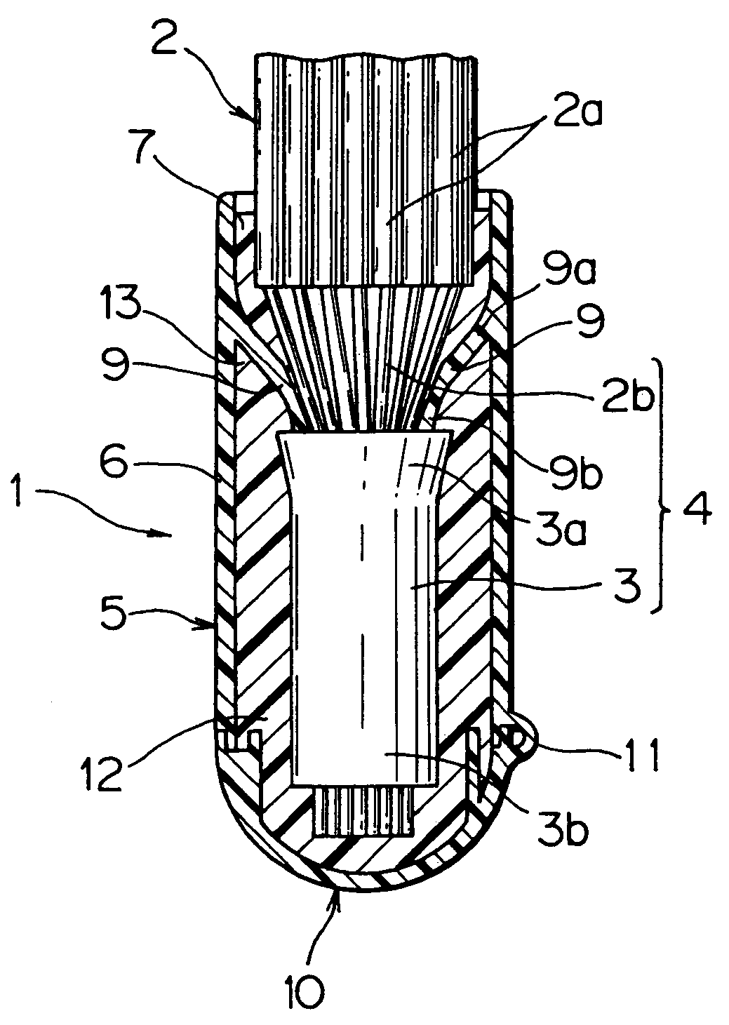
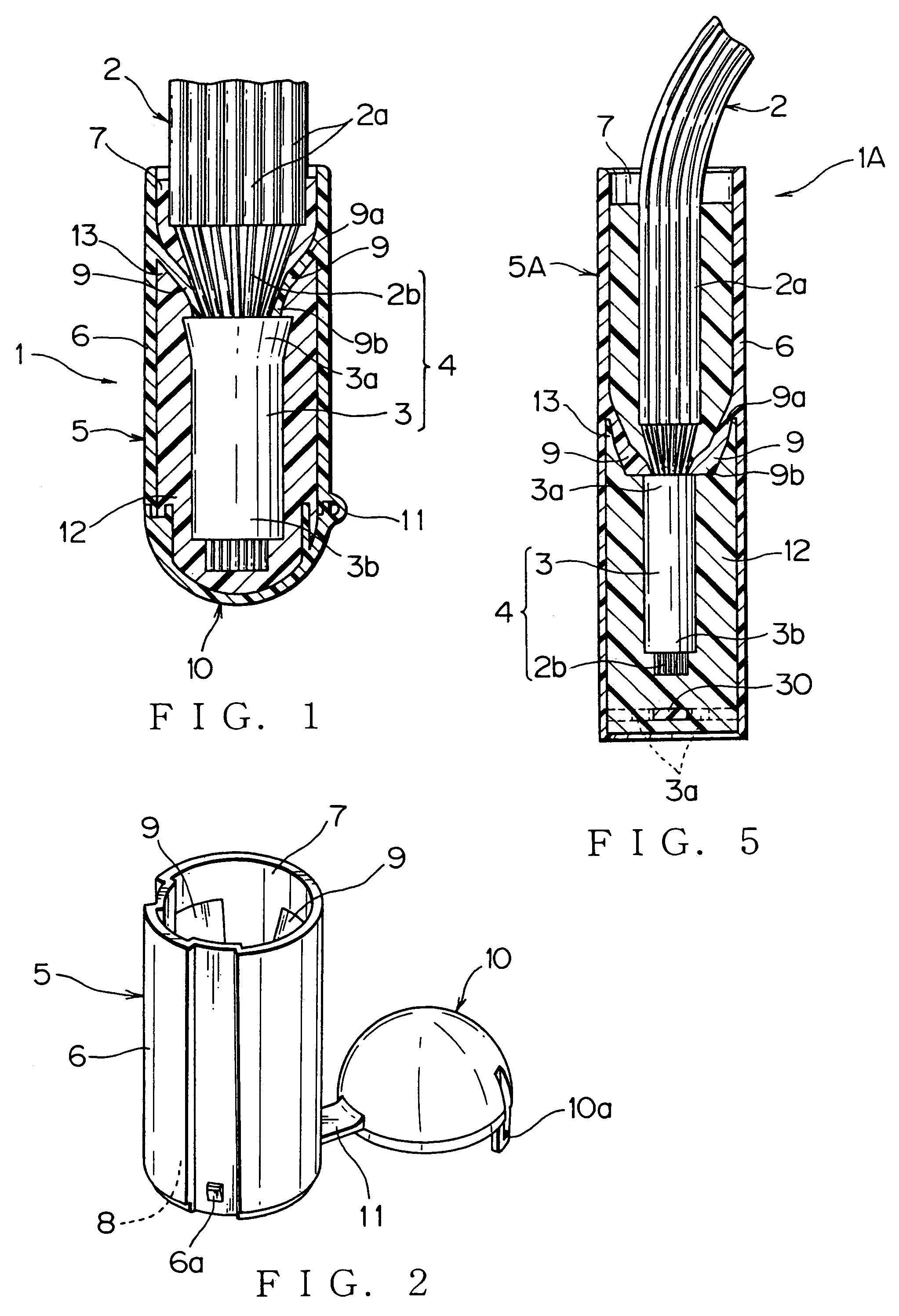
[0049]Embodiments of an insulation cap according to the present invention will be described with reference to drawings. FIG. 1 shows the insulation cap and a joined electrical wire using the insulation cap according to this invention.

[0050]The joined electrical wire 1 includes a plurality of covered wires 2, an electro-conductive sleeve 3 for joining cores 2b at terminal side of the covered wires 2, a wire joint 4, a insulation cap 5 being mounted at the wire joint 4 and insulation covers 2a near the wire joint 4, and a sealant 12 for filling inside of the insulation cap 5.

[0051]The insulation cover 2a at the terminal side of the covered wire 2 is striped to expose a predetermined length of the core 2b. The exposed cores 2b are arranged in the same direction and twisted for preventing wire elements from being loosed, and crimp-contacted with the electro-conductive sleeve 3 for joining covered wires to be connected electrically with each other. The wire joint 4 is formed with the cor...

third embodiment

[0085]an insulation cap and a joined electrical wire using the insulation cap are described with reference to FIGS. 9–14. An insulation cap 5B differs from previous embodiments in a point that the insulation cap 5B includes a small diameter receiving section 42 projecting from a bottom portion 41 of the large diameter cap main body 6. Other structuring components are common to the previous embodiments, so that the same markings are applied and detailed description is omitted herein.

[0086]The large diameter cap main body 6 has a cylindrical body to cover the insulation cover 2a near the wire joint 4. The cap main body 6 has a top opening at upper side and a bottom portion 41 at bottom side. The bottom portion 41 is formed with three fastening holes 41a for fastening a lower molding die for molding the flexible fastener 9 (FIGS. 9, 12).

[0087]The three flexible fasteners 9 are located with even intervals along a circumference of a inner wall of the cap main body 6. Thereby, the wire jo...


PUM

PropertyMeasurementUnit
electro-conductiveaaaaaaaaaa
flexibleaaaaaaaaaa
diameteraaaaaaaaaa

Abstract

An insulation cap of a wire joint of a joined electrical wire, the insulation cap including a cap main body for receiving the wire joint being formed by joining cores of a plurality of covered wires and an electro-conductive sleeve, and a flexible fastener provided on an inner wall of the cap main body for fastening the wire joint by contacting a rear end of the electro-conductive sleeve thereon. The flexible fastener is formed as an integral part of the cap main body by fastening a molding die through a hole provided at an opposite end of a joint insertion end of the cap main body. A plurality of flexible fasteners are provided axial symmetrically to extend toward a direction of inserting the wire joint from a base formed as an integral part of the inner wall of the cap main body.

Description

[0001]The priority application Number Japan Patent Application No. 2004-373112 upon which this patent application is based is hereby incorporated by reference.BACKGROUND OF THE INVENTION[0002]1. Field of the Invention[0003]This invention relates to an insulation cap being put on a wire joint formed by joining cores of a plurality of covered wires and insulation cover near the wire joint, and a joined electrical wire using the insulation cap.[0004]2. Description of the Related Art[0005]An example of the insulation cap to be put on the wire joint of a plurality of covered wires and insulation cover near the wire joint is fixed with the covered wire by winding a tape around them. FIG. 15 shows an example of such insulation caps (refer patent document 1).[0006]An insulation cap 50 shown in FIG. 15 includes a cap main body 51, which a wire joint 54 joining cores 53b together and insulation cover near the wire joint are inserted into, and a support plate 52 projecting from an opening edge...

Claims


Application Information

Patent Timeline
Patent Type & Authority Patents(United States)
IPC IPC(8): H02G15/02H01R4/70H01B7/282H01R4/20H01R4/22H01R4/66H01R13/52H01R13/58
CPCH01R4/22H01R13/5216H01R13/5845Y02A30/14
Inventor TORII, CHIEKOYAMAMOTO, TAKAYUKIOZAWA, MASATOFUKUDA, MASARU
Owner YAZAKI CORP
Why Eureka
Try Eureka