Dispersion compensating optical fiber

a technology of optical fiber and compensating fiber, applied in the direction of glass optical fiber, cladded optical fiber, instruments, etc., can solve the problems of accumulated wavelength dispersion, loss increase, transmission characteristics deterioration,

Inactive Publication Date: 2007-06-19
THE FUJIKURA CABLE WORKS LTD
View PDF29 Cites 7 Cited by
  • Summary
  • Abstract
  • Description
  • Claims
  • Application Information

AI Technical Summary

Benefits of technology

[0019]By doing this, it is possible to realize a dispersion-compensated optical fiber in which, even if it is wound in a small reel, a module loss is low, there is not an increase of a loss which is caused by a bending loss, there is not an outstanding increase of a loss which is caused by a bending loss in a long wavelength. Thus, it is possible to contain the dispersion-compensated optical fiber in a smaller module with reference to a conventional module of the dispersion-compensated optical fiber. Even if a module for a dispersion-compensated optical fiber by winding it in a small coil, it is possible to realize a module for the dispersion-compensated optical fiber which has a stable temperature characteristics such that a fluctuation of the module loss is ±0.5 dB or lower in an ordinary usage temperature range (−5° C. to +70° C.).
[0038]By doing this, it is possible to realize a dispersion-compensated optical fiber in which, even if it is wound in a small reel, a module loss is low, there is not an outstanding increase of a loss which is caused by a bending loss in a long wavelength. Thus, it is possible to contain the dispersion-compensated optical fiber in a smaller module with reference to a conventional module of the dispersion-compensated optical fiber. Compatibly, the RDS is 0.0026 nm−1 to 0.035 nm−1 in 1.57 μm to 1.63 μm; thus, is it possible to realize a dispersion-compensated optical fiber which is suitable for the S-SMF which has typically an RDS such as 0.0029 nm−1 in 1.59 μm.

Problems solved by technology

Next problem is an accumulated wavelength dispersion.
Therefore, if a signal is transmitted by using this optical fiber, the transmission characteristics deteriorates greatly by an influence of the accumulated wavelength dispersion in a long distance transmission.
However, the technology which are disclosed in the above mentioned publication and a report by an institute was not sufficient for realizing a small module while restricting an increase of a loss which is caused by a bending loss over an entire range of the usage wavelength.

Method used


Image

  • Dispersion compensating optical fiber
  • Dispersion compensating optical fiber
  • Dispersion compensating optical fiber

Examples


example 1

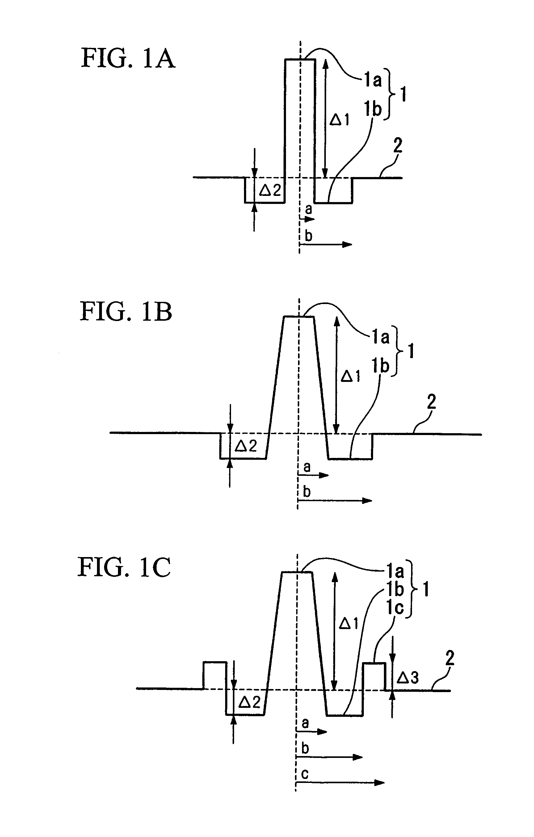
[0080]Dispersion-compensated optical fibers are produced with a W-type profile shown in FIG. 1(b) and a W-type profile with a ring shown in FIG. 1(c) according to a commonly known method such as a VAD method, an MCVD method, or a PCVD method. Under such a condition, values such as Δ1, Δ2, Δ3, b / a, c / b, a core radius, a diameter of the cladding, an outer diameter of a first coating layer, and an outer diameter of a second coating layer are made so as to be values shown in a TABLE 1 under condition that an atmospheric oxygen density should be 0.1% or lower (0.0% when it is displayed) when an ultraviolet-ray-curable resin is hardened while being drawn.

[0081]Here, a dispersion-compensated optical fiber in No. 1 is produced so as to have an outer diameter of the conventional cladding and a coating structure for a purpose of a comparison. The dispersion-compensated optical fibers shown in No. 2 to No. 6 are examples of the optical fiber according to the present invention.

[0082]

TABLE 1FIRS...

example 2

[0089]Four variations of dispersion-compensated optical fibers with a W-type profile shown in FIG. 1(c) are produced according to a commonly known method such as a VAD method, an MCVD method, or a PCVD method. Under such a condition, values such as Δ1, Δ2, Δ3, b / a, c / b, and a core radius are made so as to be values shown in a TABLE 4 under condition that an atmospheric oxygen density should be 0.1% or lower (0.0% when it is displayed) when an ultraviolet-ray-curable resin is hardened while being drawn.

[0090]Here, a dispersion-compensated optical fibers in No. 7 to No. 9 are produced so as to have conventional dispersion characteristics for a purpose of a comparison. The dispersion-compensated optical fiber shown in No. 2 is an example of the optical fiber according to the present invention.

[0091]

TABLE 4FIRSTSECONDCLADDINGCOATINGCOATINGCOREOUTEROUTEROUTERSURFACERADIUSDIAMETERDIAMETERCIAMETERVISCOSITYNo.Δ1(%)Δ2(%)Δ3(%)b / ac / b(μm)(μm)(μm)(μm)(gf / mm)22.00−0.460.362.71.56.4901351750.171.6...

example 3

[0098]Five variations of dispersion-compensated optical fibers with a W-type profile shown in FIG. 1(b) or with a W-type profile with ring as shown in FIG. 1(c) are produced according to a commonly known method such as a VAD method, an MCVD method, or a PCVD method Under such a condition, values such as Δ1, Δ2, Δ3, b / a, c / b, a core radius, a diameter of the cladding, an outer diameter of a first coating layer, and an outer diameter of a second coating layer are made so as to be values shown in a TABLE 1 under condition that an atmospheric oxygen density should be 0.1% or lower (0.0% when it is displayed) when an ultraviolet-ray-curable resin is hardened while being drawn.

[0099]Here, a dispersion-compensated optical fibers in No. 12 to No. 13 are produced so as to have conventional dispersion characteristics for a purpose of a comparison. The dispersion-compensated optical fiber shown in No. 2, No. 10, and No. 11 are examples of the optical fiber according to the present invention.

[0...


PUM


Abstract

A dispersion-compensated optical fiber which does not cause an increase in a loss if it is wound in a small reel and has a stable temperature characteristics is provided, wherein, in a wavelength range from. A dispersion-compensated optical fiber is formed such that, in at least a wavelength between 1.53 to 1.63 μm, a bending loss of with a 20 mm bending diameter is 5 dB / m or lower, a wavelength dispersion is −120 ps / nm / km or lower, a cut-off wavelength under a usage condition is 1.53 μm or lower, an outer diameter of the cladding is 80 to 100 μm, an outer diameter of a coating is 160 to 200 μm, and a viscosity of a surface of a coating resin is 10 gf / mm or lower. It is set such that b / a is 1.5 to 3.5, c / b is 1.2 to 2.0, a radius of a core is 4 to 8 μm, Δ1 is +1.6% to +2.6%, Δ2 is −0.30% to −1.4%, and Δ3 is −0.30% to +1.0%. Young's modulus of a first coating layer is 0.15 kgf / mm2 or lower and its thickness is 20 to 30 μm. Young's modulus of a second coating layer is 50 kgf / mm2 or lower and its thickness is 15 to 30 μm.

Description

[0001]This is a National Stage entry of International Application PCT / JP03 / 03004, with an international filing date of Mar. 13, 2003, which was published under PCT Article 21(2) in Japanese, and the disclosure of which is incorporated herein by reference. Further, International Application PCT / JP03 / 03004 is based on Japanese Patent Application Nos. 2002-069077 and 2003-057013, filed in Japan on Mar. 13, 2002 and Mar. 4, 2003, respectively, the disclosures of which are incorporated herein by reference.TECHNICAL FIELD[0002]The present invention relates to a dispersion-compensated optical fiber which compensates a wavelength dispersion for a 1.3 μm bandwidth zero-dispersion single mode optical fiber (Standard Single Mode Fiber, hereinafter called an “S-SMF” for short) which has a zero-dispersion wavelength in 1.3 μm bandwidth or a non-zero dispersion shift optical fiber (Non-Zero Dispersion Shifted Fiber, hereinafter called as “NZ-DSF” for short. In particular, the present invention re...

Claims


Application Information

Patent Timeline
Patent Type & Authority Patents(United States)
IPC IPC(8): G02B6/02G02B6/036G02B1/00G02B6/44
CPCG02B6/02261G02B6/02395G02B6/03644G02B6/03627G02B6/0281
Inventor AIKAWA, KAZUHIKOSHIMIZU, SHOGOSUZUKI, RYUJINAKAYAMA, MASAKAZUHIMENO, KUNIHARU
Owner THE FUJIKURA CABLE WORKS LTD
Why Eureka
Try Eureka