Voltage-controlled oscillator for producing multiple frequency bands

A voltage-controlled oscillation, multi-band technology, applied in power oscillators, electrical components, etc., can solve the problems of unstable oscillation frequency or oscillation level temperature characteristics, difficulty in providing zero potential, unstable electronic switch 14, etc. Reduce the effect of interference

Inactive Publication Date: 2002-07-10
PANASONIC CORP
View PDF0 Cites 5 Cited by
  • Summary
  • Abstract
  • Description
  • Claims
  • Application Information

AI Technical Summary

Problems solved by technology

[0007] However, in this existing configuration, the switching of the electronic switch 14 is only to switch the power supply Vcc or the ground potential to the frequency band switching terminal 13, especially when the ground potential is provided, it is difficult to provide a true zero potential, so that it works in a tiny positive potential state.
As a result, there is a problem that the electronic switch 14 is in an unstable state because it is not completely turned off, so that the temperature characteristics of the oscillation frequency or oscillation level are in an unstable state.

Method used


Image

  • Voltage-controlled oscillator for producing multiple frequency bands
  • Voltage-controlled oscillator for producing multiple frequency bands
  • Voltage-controlled oscillator for producing multiple frequency bands

Examples


Embodiment 1

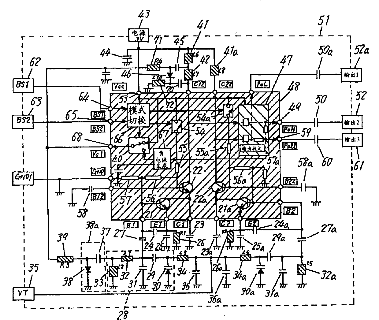
[0044] Fig. 1 is a circuit diagram of a multi-band voltage controlled oscillator according to Embodiment 1 of the present invention. Illustrate with an unbalanced oscillator. In Figure 1, 21 is the oscillation transistor, which is connected to the buffer transistor for emitter-to-ground amplification, 23 is a capacitor, which connects the collector of the oscillation transistor 21 to a high-frequency ground, and 24 is inserted and connected between the base and emitter of the oscillation transistor 21 The capacitor, 25 is a capacitor connected between the emitter and the ground (in the case of high frequency, between the emitter and the collector), and 26 is a resistor connected between the emitter and the ground. The coupling capacitor 27 and the resonant circuit 28 (described later) are connected in series, and are connected between the base of the oscillation transistor 21 and the ground (connected between the base and the ground in the case of high frequency) to form a Colpitt...

Embodiment 2

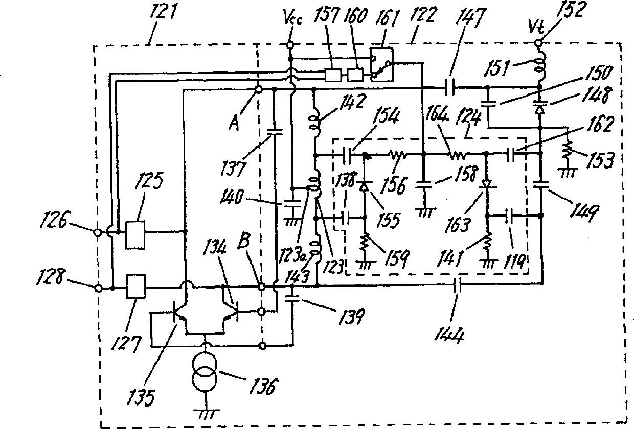
[0060] Hereinafter, the second embodiment of the present invention will be described using a balanced oscillator as an example based on the drawings.

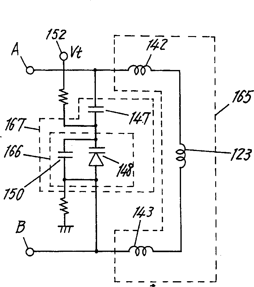
[0061] 2 is a circuit diagram of the multi-band voltage controlled oscillator of the present invention. In a balanced amplifier circuit 121 formed of a transistor, a resonance circuit 122 formed of an inductor and a capacitor is connected between one terminal A and the other terminal B The switching means 124 is connected to both ends of the inductor 123 forming the resonance circuit 122. The aforementioned terminal A is connected to the output terminal 126 through a buffer circuit 125 formed by a transistor, and the other terminal B is connected through a buffer circuit formed by a transistor. 127 is connected to the output terminal 128. Therefore, the buffer circuit 125 and the buffer circuit 127 are the same circuit, and FETs can also be used for these transistors.

[0062] The power supply Vcc introduced from the midpoint of th...


PUM


Abstract

An object of the present invention is to provide a multi-band voltage-controlled oscillator in which switching means can certainly be turned on and off. For achieving the above object, the oscillator of the present invention includes a negative source generator (67) coupled to an output of a buffer transistor (22) from which an oscillation frequency of an oscillating transistor (21) is released, switching means (40) for selectively switching between an output of the negative source generator (67) and a positive power source, and mode switching means (66) receiving an output frequency switching signal from the outside. An output of the switching means (40) controls an opening and short-circuiting operation of first switching means (38a) to selectively release oscillation outputs in a low frequency band and high frequency band from an output port (49).

Description

Technical field [0001] The invention relates to a multi-band voltage controlled oscillator used in a mobile communication device Background technique [0002] In recent years, mobile communications have entered a stage of rapid popularization, and the originally allocated frequency bands are no longer sufficient to provide services. Therefore, new frequency services have been introduced in the 1.5-2GHz band. Therefore, it is required for mobile communication terminals to be able to adapt to these two frequency bands. On the other hand, semiconductor technology has also made significant progress. Under this background, oscillators for mobile communications are required to oscillate in at least three frequency bands and are suitable for use as voltage controlled oscillators for semiconductor integrated circuits. [0003] Next, a multi-band voltage controlled oscillator used in a conventional mobile communication device will be described. The existing multi-band voltage controlled o...

Claims


Application Information

Patent Timeline
Patent Type & Authority Applications(China)
IPC IPC(8): H03B1/00H03B5/12H03B5/18
CPCH03B5/1243H03B5/1262H03B5/1209H03B5/1231H03B2201/025
Inventor 赤冢辉元
Owner PANASONIC CORP
Why Eureka
Try Eureka