Gas turbine combustion chamber made of CMC and supported in a metal casing by CMC linking members

a technology of cmc and connecting members, which is applied in the direction of machines/engines, mechanical equipment, lighting and heating apparatus, etc., can solve the problems of connecting the cmc combustion chamber to the metal casing, real difficulties, and inconvenient use of metals for the walls of the combustion chamber

Active Publication Date: 2007-06-26
SN DETUDE & DE CONSTR DE MOTEURS DAVIATION S N E C M A
View PDF15 Cites 72 Cited by
  • Summary
  • Abstract
  • Description
  • Claims
  • Application Information

AI Technical Summary

Benefits of technology

[0008]By limiting the dimensions of the zones of brazing, it is possible to make it easier to control the spacings between the surface portions to be brazed together, and thus avoid irregularities in brazing thickness. It is thus possible to obtain effective bonding by brazing.

Problems solved by technology

The use of metals for combustion chamber walls can then become inappropriate, even when implementing cooling as effectively as possible.
A problem which then arises is that of connecting the CMC combustion chamber to the metal casing, because of the differences between their coefficients of thermal expansion.
However, the brazed connection between the CMC ferrule and the annular wall of the combustion chamber leads to real difficulties.
Unfortunately, given the processes whereby CMC parts are manufactured, the dimensional tolerances thereof are greater than is the case for metal parts.
It is therefore very difficult to guarantee uniform spacing between two complete annular surfaces that are to be connected together by brazing.

Method used


Image

  • Gas turbine combustion chamber made of CMC and supported in a metal casing by CMC linking members
  • Gas turbine combustion chamber made of CMC and supported in a metal casing by CMC linking members
  • Gas turbine combustion chamber made of CMC and supported in a metal casing by CMC linking members

Examples


Embodiment Construction

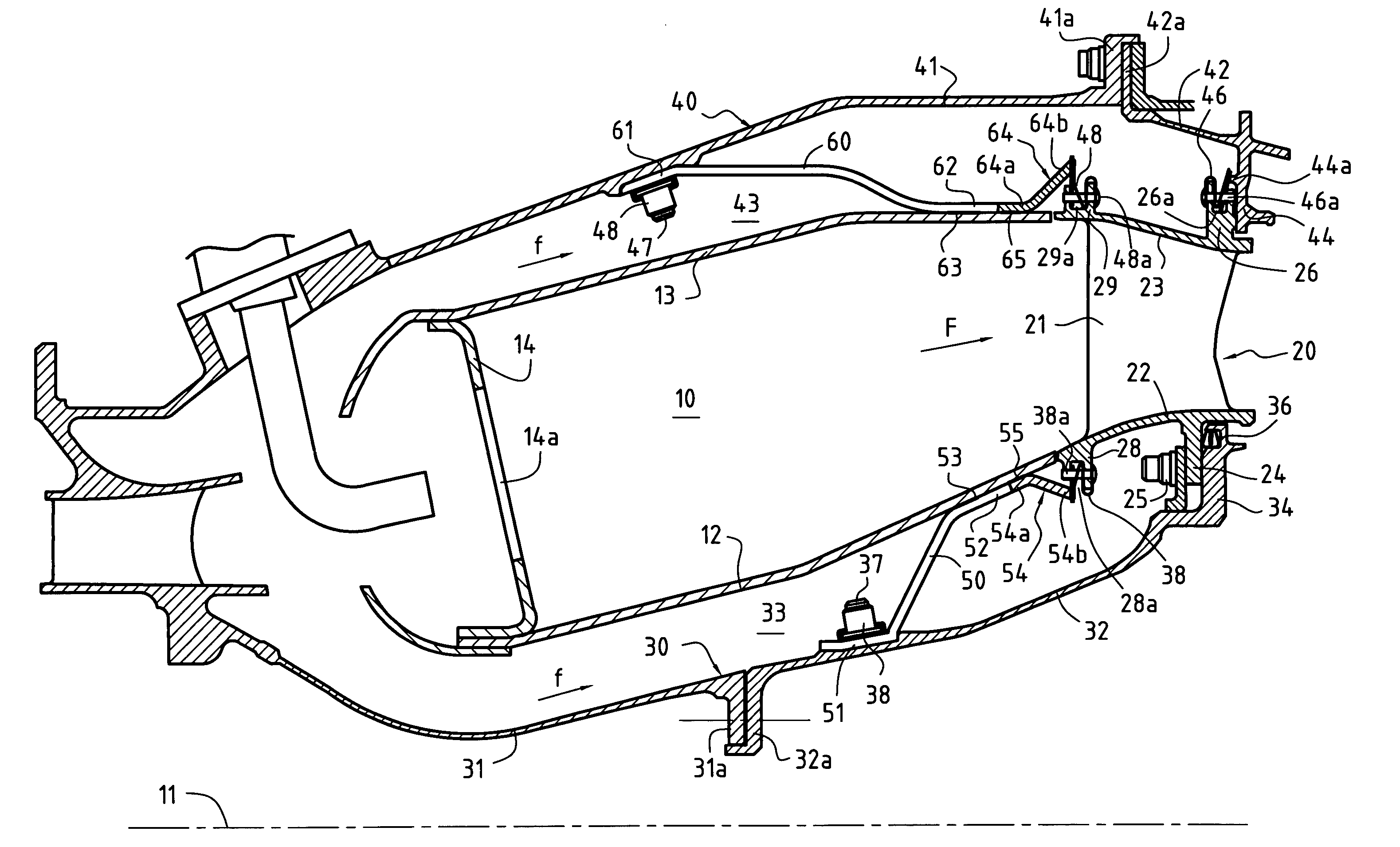
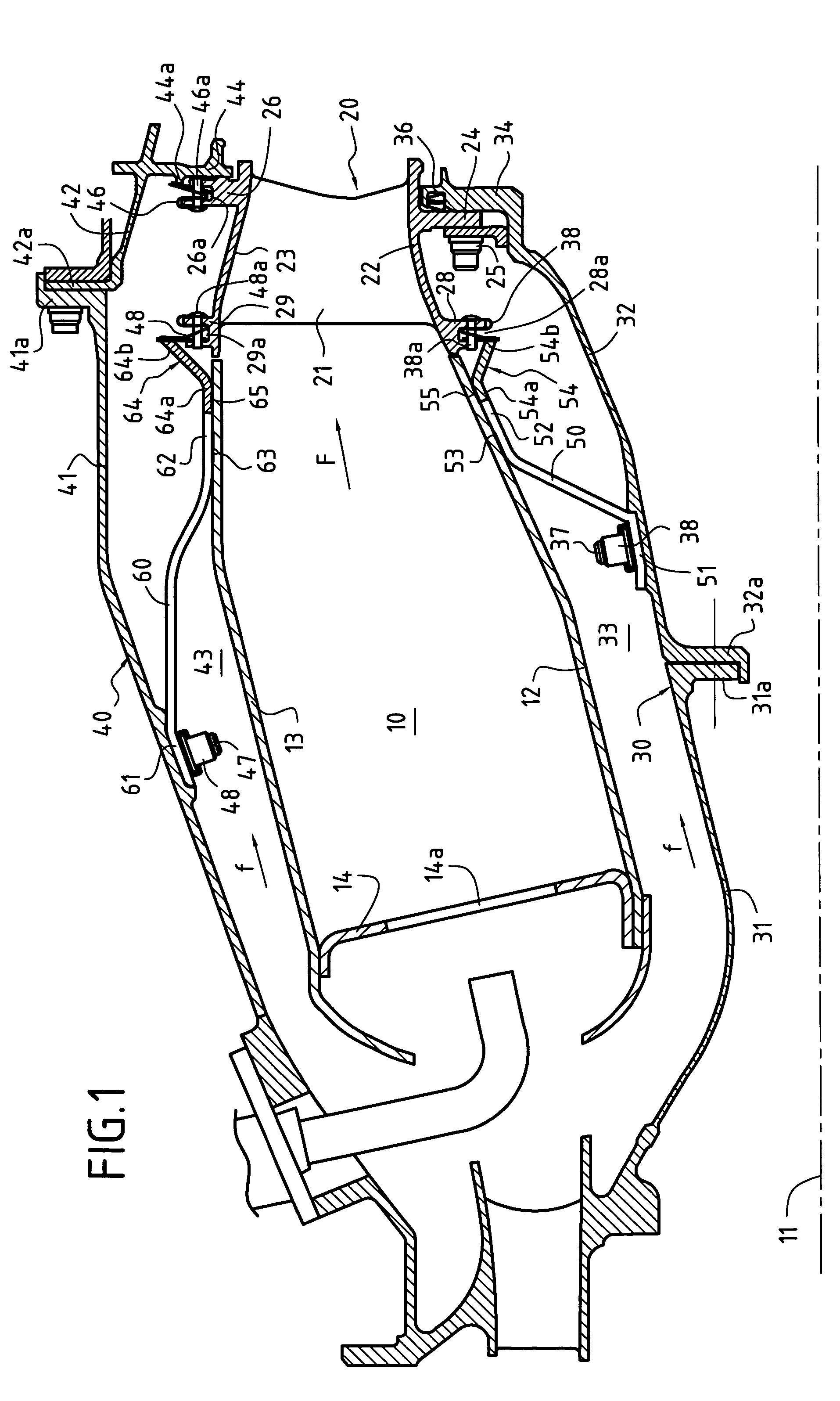
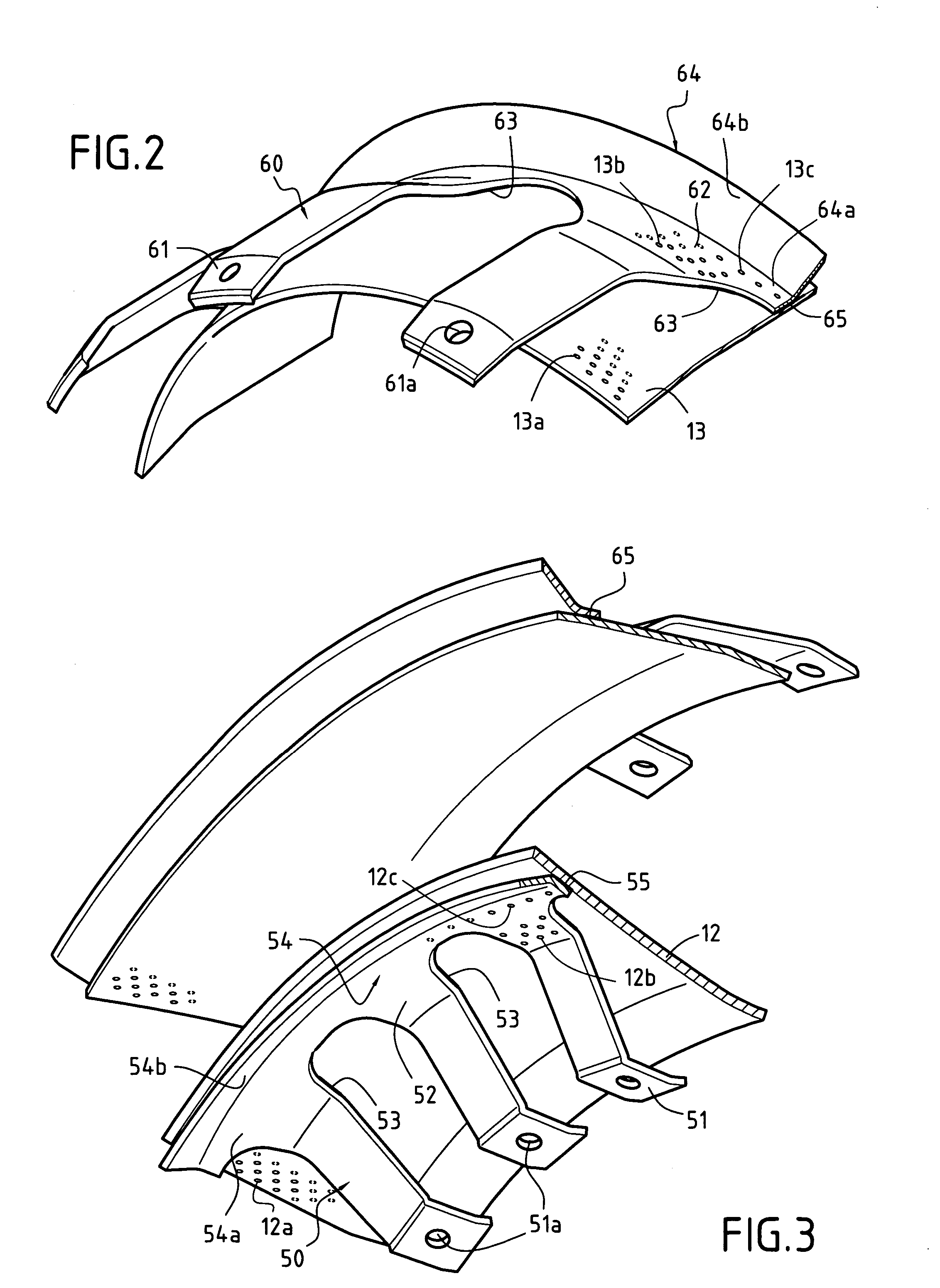
[0022]FIG. 1 is an axial half-section of a portion of a gas turbine comprising an annular combustion chamber 10, a high pressure turbine nozzle 20 disposed immediately downstream from the combustion chamber 10, a metal casing comprising inner and outer metal shrouds 30 and 40, and inner and outer linking tabs 50 and 60 holding the chamber 10 inside the metal casing. Below, the terms “upstream” and “downstream” are used relative to the flow direction (arrow F) of the gas stream coming from the chamber 10.

[0023]The combustion chamber 10 is defined by an inner annular wall 12 and an outer annular wall 13 sharing a common axis 11, and by an end wall 14 secured to the walls 12 and 13. In well-known manner, the end wall 14 presents openings 14a that are distributed around the axis 11 to house injectors for injecting fuel and oxidizer into the chamber 10. The walls 12 and 13 of the chamber 10 are made of CMC, e.g. a composite material having an SiC matrix, and optionally the wall 14 is mad...


PUM


Abstract

The annular combustion chamber having ceramic matrix composite material walls is mounted inside a metal casing by linking members fastened to the chamber by brazing. The linking members comprise a plurality of inner linking tabs and a plurality of outer linking tabs connecting the chamber to the inner and outer metal shrouds of the casing, each linking tab has a first portion fastened to the outside surface of a wall of the combustion chamber by brazing, the first portions of the linking tabs being spaced apart from one another circumferentially so that the brazed connections between the chamber and the linking members occupy a set of limited zones that are spaced apart from one another.

Description

BACKGROUND OF THE INVENTION[0001]The present invention relates to mounting a combustion chamber having a wall made of ceramic matrix composite (CMC) material inside a metal casing, in a gas turbine. The field of application of the invention is more particularly that of industrial gas turbines and of turbojets or turboprops for airplanes.[0002]It is common practice for a gas turbine combustion chamber to be made of metal and to be mounted or secured inside a metal casing by linking members, ferrules or tabs, that are made of metal. Using a metal for the wall of the chamber is appropriate so long as it is possible to ensure effective cooling of said wall. However, there is a need to increase temperatures within the combustion chamber in order to increase the efficiency of the gas turbine and reduce polluting emissions. The use of metals for combustion chamber walls can then become inappropriate, even when implementing cooling as effectively as possible. Proposals have therefore been m...

Claims


Application Information

Patent Timeline
Patent Type & Authority Patents(United States)
IPC IPC(8): F23R3/60F23R3/00
CPCF23R3/007F23R3/60F05C2203/08F02C7/20
Inventor AUMONT, CAROLINECONETE, ERICDE SOUSA, MARIOHERNANDEZ, DIDIER
Owner SN DETUDE & DE CONSTR DE MOTEURS DAVIATION S N E C M A
Why Eureka
Try Eureka