Double-sheath pipe for transporting fluids, provided with a device for limiting propagation of a buckle of the outer tube and method for limiting propagation

a technology of double-walled (or double-sheath) pipes and outer pipes, which is applied in the direction of rigid pipes, flexible pipes, pipe laying and repair, etc., can solve the problems of dissipation of propagation energy, and achieve the effect of simple manufacture and mounting

Inactive Publication Date: 2007-06-26
COFLEXIP
View PDF15 Cites 8 Cited by
  • Summary
  • Abstract
  • Description
  • Claims
  • Application Information

AI Technical Summary

Benefits of technology

[0021]It is an objective of the invention to provide a propagation arrestor device for a reelable double-

Problems solved by technology

However, to arrest the propagation of the buckle, the devi

Method used


Image

  • Double-sheath pipe for transporting fluids, provided with a device for limiting propagation of a buckle of the outer tube and method for limiting propagation
  • Double-sheath pipe for transporting fluids, provided with a device for limiting propagation of a buckle of the outer tube and method for limiting propagation
  • Double-sheath pipe for transporting fluids, provided with a device for limiting propagation of a buckle of the outer tube and method for limiting propagation

Examples


Embodiment Construction

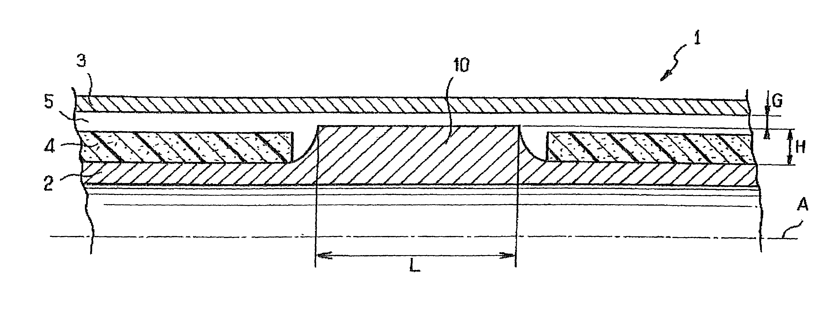
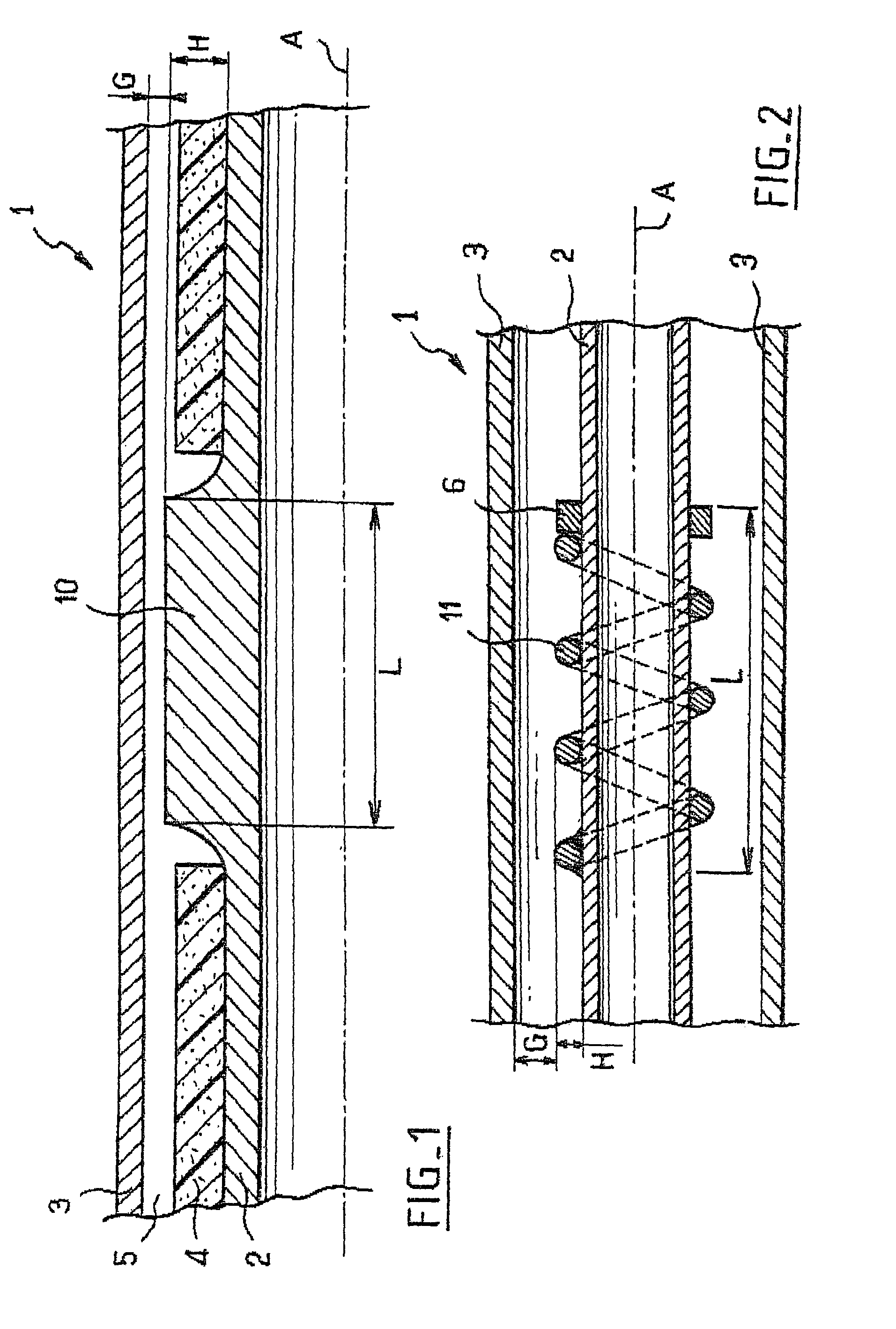
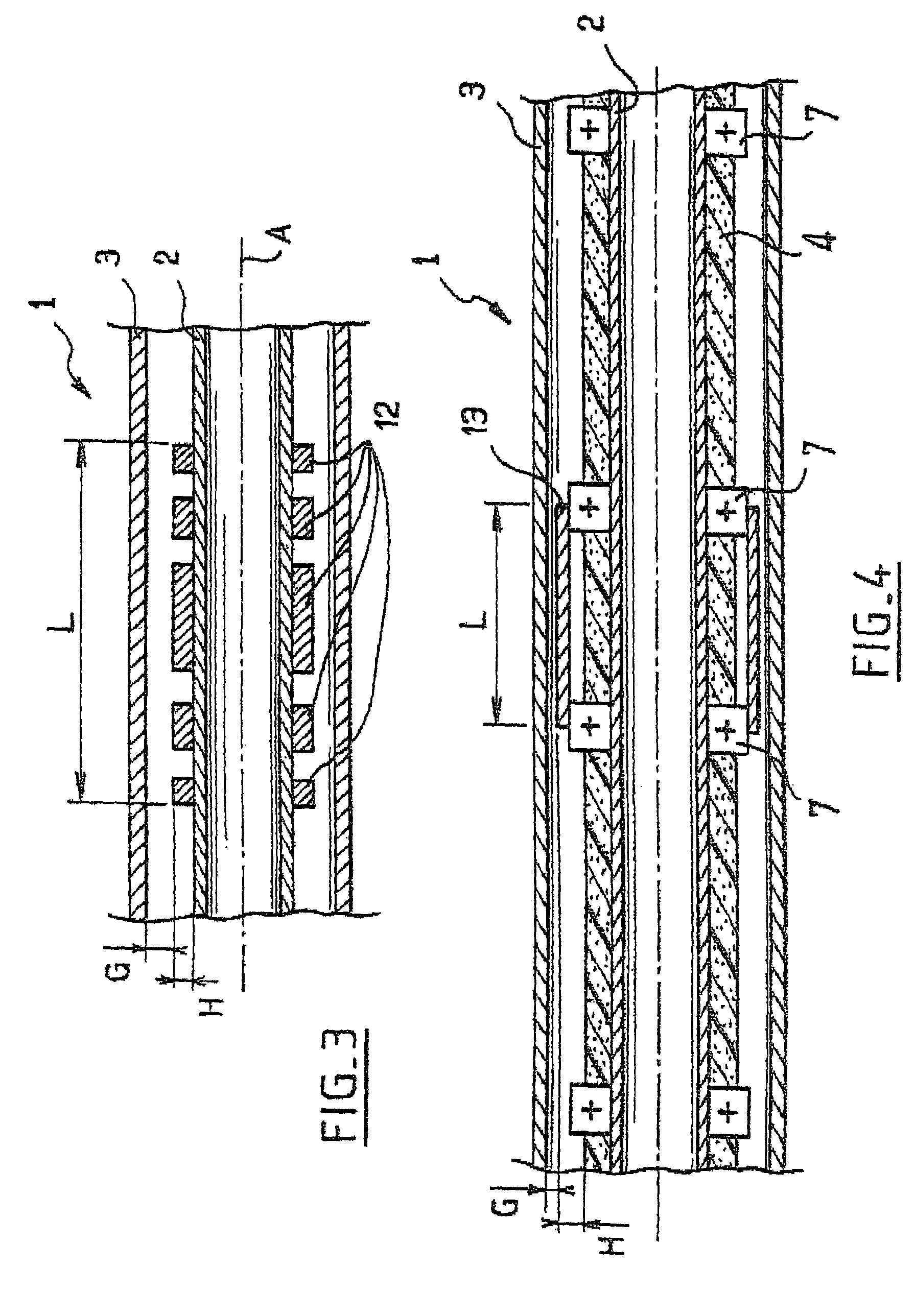
[0043]The double-walled rigid pipe 1 of longitudinal axis A, shown partially in FIG. 1, comprises an inner wall or tube 2 (the “flowline”), the diameter and the nature of the material of which are chosen according to the fluid flowing in the said inner tube, especially according to the temperature and pressure of the said fluid, and an outer wall or tube 3 (the “carrier pipe”) which is slipped over the inner tube 2. The outer tube 3 has an outside diameter which is oversized with respect to the inner tube 2 in order to allow a thermal insulation to be placed in the annular space 5 and has a thickness which makes it possible to withstand the hydrostatic pressure which is exerted on the said outer tube 3.

[0044]According to the invention, the inner tube 2 comprises a cylindrical section 10 of length L with a thickness increased towards the outside by an amount H, leaving a distance G to the outer tube. G is, by calculation or by experiment, greater than the value above which a buckle o...


PUM


Abstract

The invention concerns a double-sheath rigid pipe for transporting hydrocarbons consisting of two respectively inner (2) and outer (3) coaxial tubes separated by an annular gap (5), said pipe being adapted to be wound and comprising a device limiting the propagation of a deformation occurring on the outer tube, wherein a radial stop device (10) linked to the inner tube (2) but not linked to the outer tube (3) allows a localized collapse of value G of the outer tube, G being selected to stop the propagation of a deformation of the outer tube (3).

Description

BACKGROUND OF THE INVENTION[0001]The present invention relates to a device and to a method for limiting or arresting the propagation of a buckle in a double-walled (or double-sheath) pipe consisting of two, respectively inner and outer, coaxial tubes separated by an annular space, this pipe being a rigid pipe for transporting fluids such as hydrocarbons, and designed to be submerged.[0002]A rigid pipe or tube is laid on the seabed usually from a vessel called a pipelaying barge. The laying is called S-laying when the pipe adopts the shape of an S between the pipelaying barge and the seabed and it is called J-laying when the pipe adopts the shape of a J. In the latter case, a guide ramp is provided on the pipelaying barge, which ramp may sometimes be partially immersed in the water.[0003]The rigid pipe to be laid is stored on the pipelaying barge either in pipe sections of a given but relatively short length, the pipe sections being joined together as the laying progresses, or it is ...

Claims


Application Information

Patent Timeline
IPC IPC(8): F16L9/00F16L9/18F16L57/02
CPCF16L9/18F16L57/02
Inventor BASTARD, ANTOINEBELL, MIKE
Owner COFLEXIP
Why Eureka
Try Eureka