Image forming apparatus with dust collector

a technology of dust collector and forming apparatus, which is applied in the direction of chemistry apparatus and processes, separation processes, printing, etc., can solve the problems of insufficient wiping part, insufficient air sucked, and blockage of the ink jet head nozzle, etc., and achieve the effect of increasing the efficiency of air sucked

Inactive Publication Date: 2007-06-26
S PRINTING SOLUTION CO LTD
View PDF4 Cites 0 Cited by
  • Summary
  • Abstract
  • Description
  • Claims
  • Application Information

AI Technical Summary

Benefits of technology

[0010]The present general inventive concept provides an image forming apparatus including a dust collecting part capable of effectively adsorbing impurities, such as dust, particles, ink mists, etc., generated by an ink jet head. In particular, the present general inventive concept may be used to adsorb impurities generated by an wide array type ink jet head.
[0011]The present general inventive concept provides an image forming apparatus including a dust-collecting part on which maintenance is made easy by allowing impurities to be adsorbed and readily removed.

Problems solved by technology

As a result, a nozzle of the ink jet head may become blocked and printing quality may deteriorate.
In addition, since the ink remaining on the ink jet head agglomerates and blocks the nozzle when the printing operation is not performed for an extended period of time, it becomes necessary to store the ink jet head in an enclosed state when the ink jet head is not in use.
In addition, although the impurities should be more thoroughly removed from the wide array type ink jet head due to an increased probability of contamination of the wide array type ink jet head, a wiping part is insufficient to remove the impurities, because wiping the wide array type ink jet head becomes more difficult than the conventional ink jet head.

Method used


Image

  • Image forming apparatus with dust collector
  • Image forming apparatus with dust collector
  • Image forming apparatus with dust collector

Examples


Embodiment Construction

[0035]Reference will now be made in detail to the embodiments of the present general inventive concept, examples of which are illustrated in the accompanying drawings, wherein like reference numerals refer to the like elements throughout. The embodiments are described below in order to explain the present general inventive concept by referring to the figures.

[0036]Hereinafter, an embodiment of an image forming apparatus provided with a dust collecting part in accordance with the present general inventive concept will be described in conjunction with the accompanying drawings.

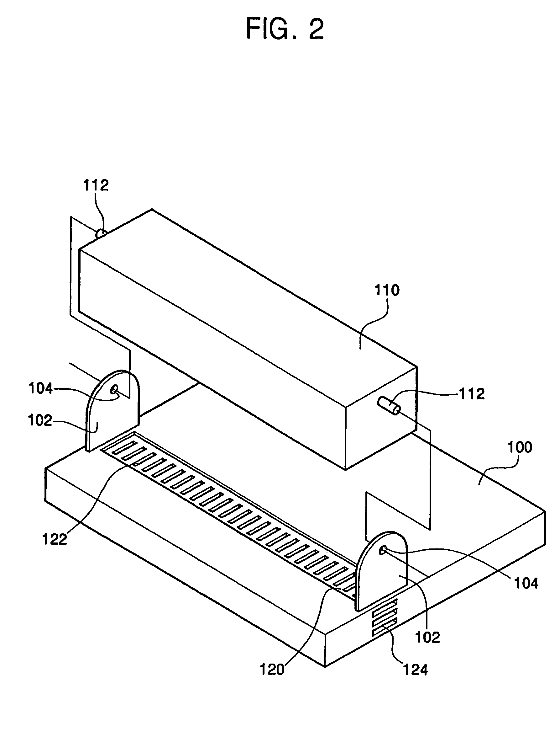
[0037]Referring to FIG. 2, an example of an image forming apparatus having a dust collector in accordance with the present general inventive concept is shown. While not shown, this embodiment has a main body case provided with various manipulating buttons, a display part such as an LCD, and a controller that controls operation of the apparatus. The description of these parts will be omitted.

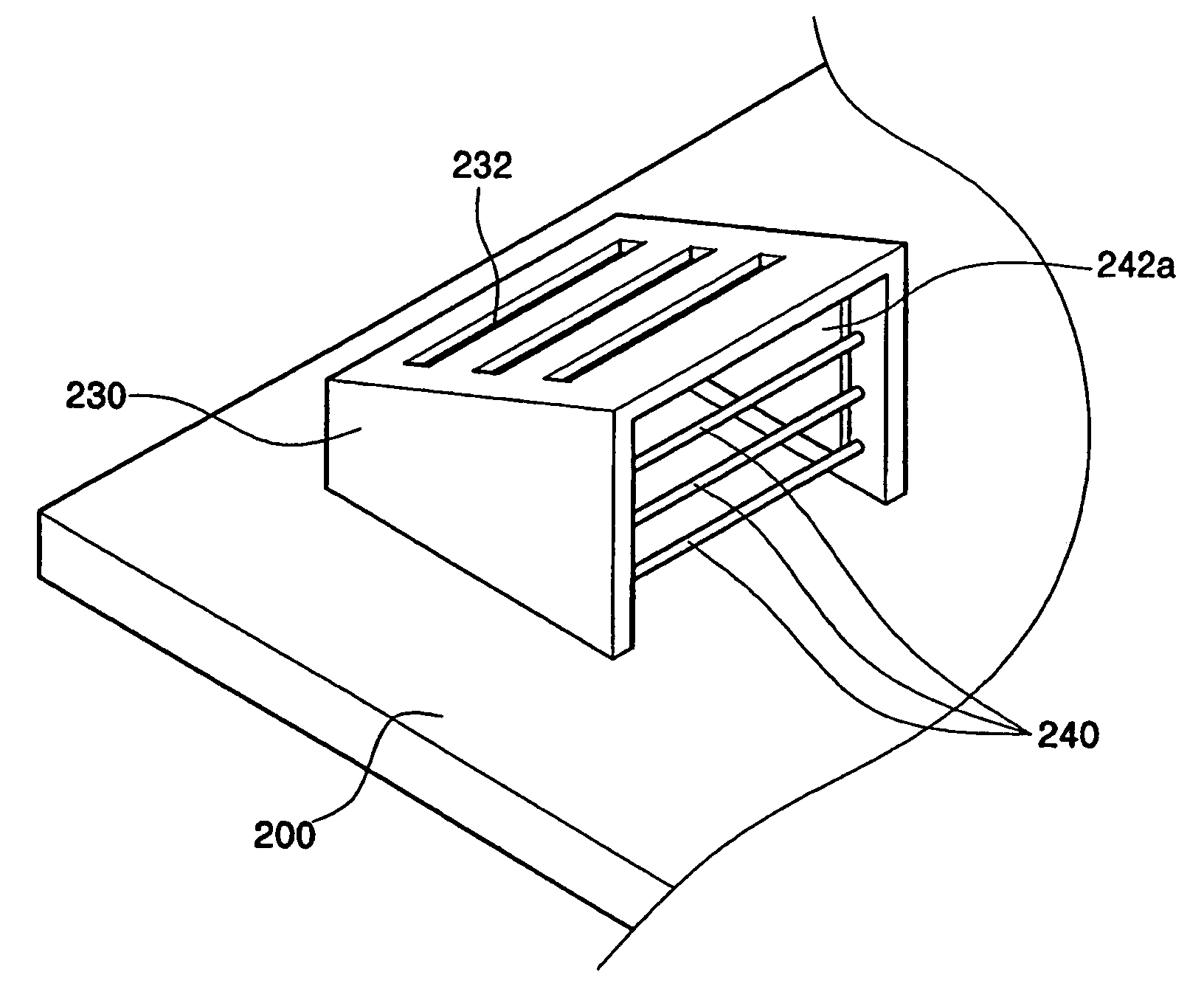
[0038]In FIG. 2, a re...


PUM

PropertyMeasurementUnit
lengthaaaaaaaaaa
air pressureaaaaaaaaaa
polarityaaaaaaaaaa

Abstract

An image forming apparatus provided with a dust collecting part includes an ink cartridge having a wide array type ink jet head that is capable of ejecting ink over an entire lateral line that is perpendicular to a conveying direction of a recording medium at a time, and a main body case that supports the ink cartridge, a duct located under the wide array type ink jet head to extend in a longitudinal direction of the wide array type ink jet head; and a dust collecting part including a charging part disposed in the duct to charge impurities and electrodes disposed in the duct to adsorb the charged impurities The image forming apparatus includes a dust-collecting part that adsorbs the impurities over an entire region of the wide array type ink jet head, thereby effectively removing the impurities generated in large quantities and increasing a life span and a reliability of image forming apparatuses, since the dust collecting part is securely maintained during operation.

Description

CROSS-REFERENCE TO RELATED APPLICATIONS[0001]This application claims the benefit of Korean Patent Application No. 2004-62948filed on Aug. 10, 2004, the disclosure of which is hereby incorporated herein by reference in its entirety.BACKGROUND OF THE INVENTION[0002]1. Field of the Invention[0003]The present general inventive concept relates to an image forming apparatus having a dust collecting part, and more particularly, to an image forming apparatus having an ink cartridge with a wide array type ink jet head that is capable of printing an entire lateral line of a recording medium at a time, and a device that removes impurities, such as ink mists, dust, or particles, from the image forming apparatus.[0004]2. Description of the Related Art[0005]An ink jet printer is a device for printing a desired image or text by ejecting ink stored in a cartridge onto a recording medium through an ejecting part, typically a nozzle of an ink jet head. Ink jet printers have been widely used due to th...

Claims


Application Information

Patent Timeline
Patent Type & Authority Patents(United States)
IPC IPC(8): B41J2/165B41J2/17B41J2/175
CPCB41J29/17B01D46/0032B41J2/165B41J2/17513B41J2/17563
Inventor LIM, GUI-TAEKKIM, TAE-KYUN
Owner S PRINTING SOLUTION CO LTD
Why Eureka
Try Eureka