Switch assembly for an electrical panel

a technology of electrical panels and switches, which is applied in the direction of switchgear with a retractable carriage, contact mechanisms, contact devices, etc., can solve the problems of interrupting the illumination of indicator lights, and achieve the effect of convenient installation

Active Publication Date: 2007-07-03
RELIANCE CONTROLS
View PDF7 Cites 32 Cited by
  • Summary
  • Abstract
  • Description
  • Claims
  • Application Information

AI Technical Summary

Benefits of technology

[0005]It is an object of the present invention to provide an interlock assembly that can be readily installed in an electrical panel. It is another object of the present invention to provide a switch assembly configured to selectively control a supply of electrical power from one of a utility service and a generator power supply. It is another object of the invention to provide a switch ...

Problems solved by technology

When the indicator light is illuminated, movement of interlock handle to cause electrical connection of the electrical panel to receive electrical power from the first power supply also si...

Method used


Image

  • Switch assembly for an electrical panel
  • Switch assembly for an electrical panel
  • Switch assembly for an electrical panel

Examples


Embodiment Construction

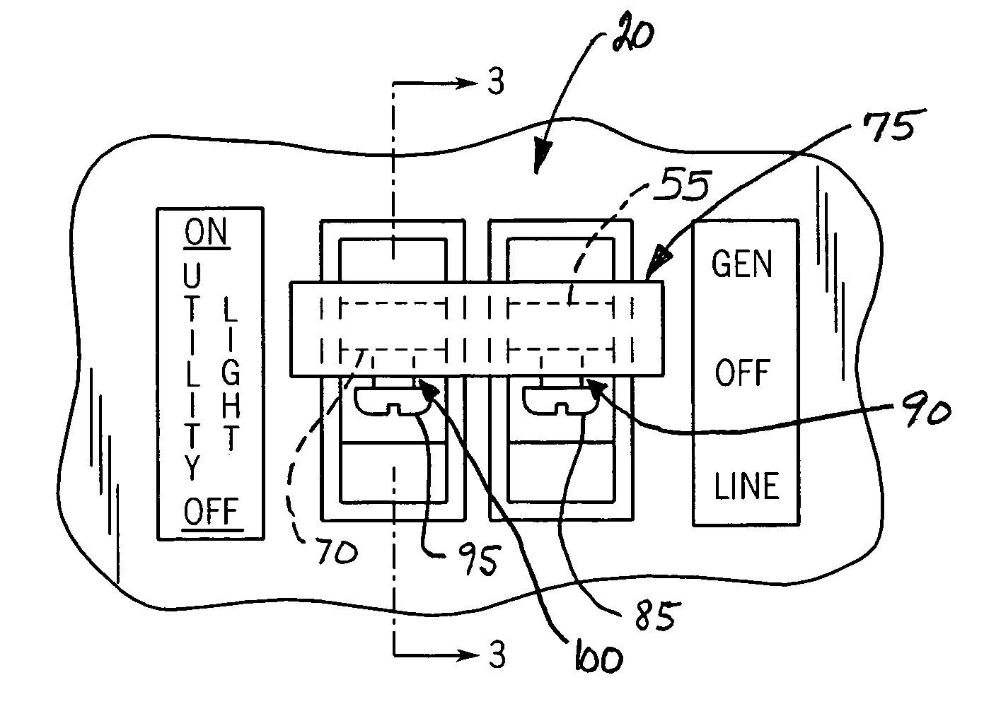
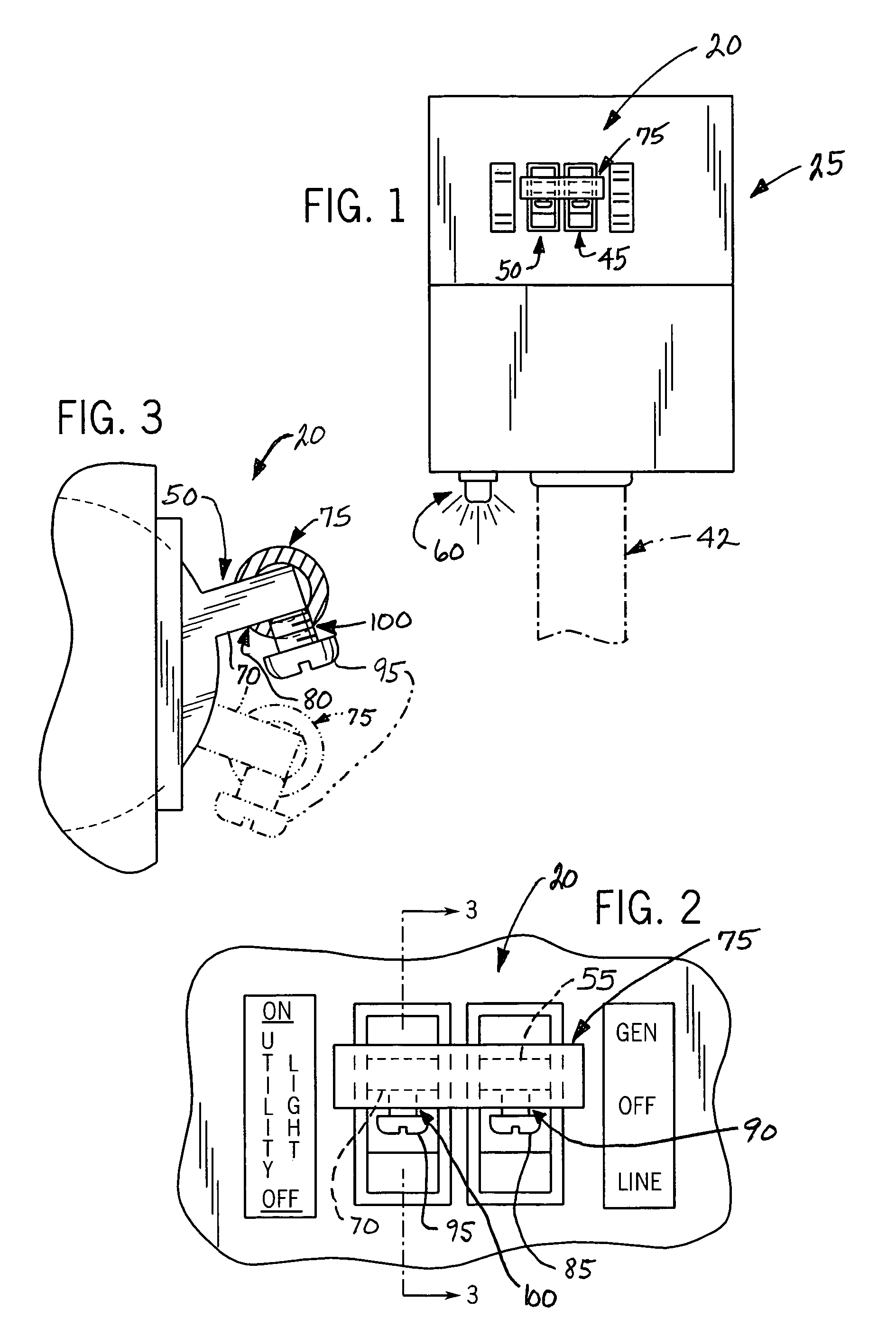
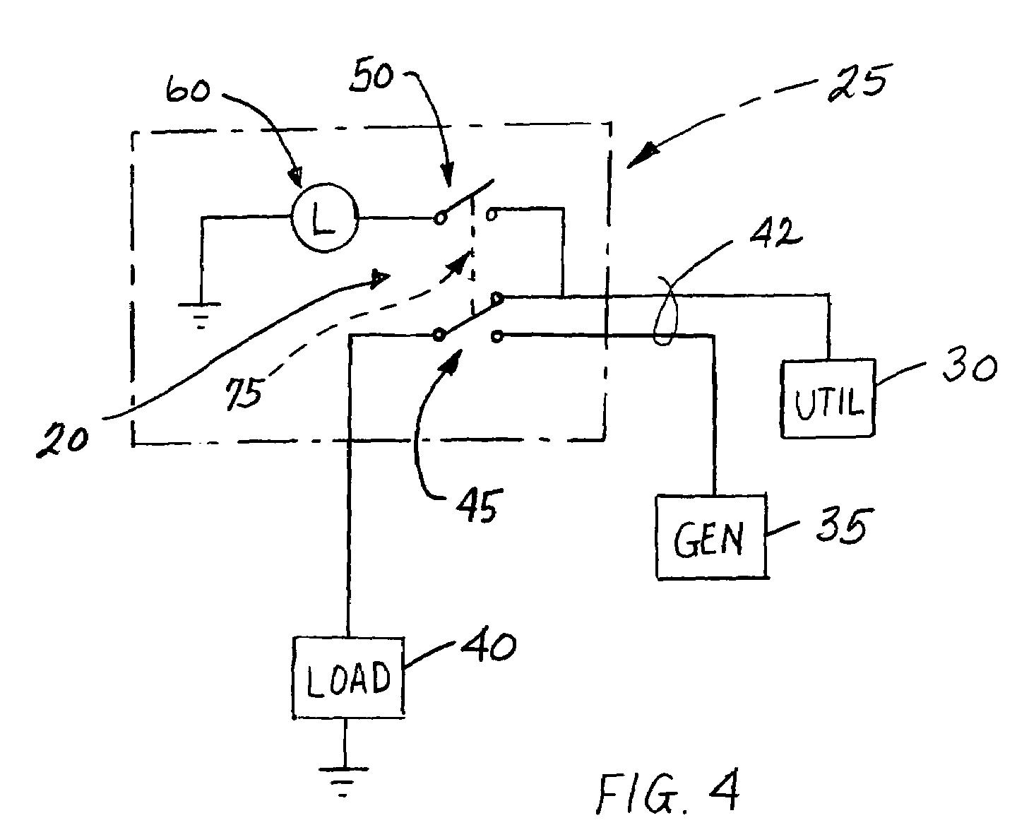
[0015]FIG. 1 illustrates a preferred embodiment of a switch assembly 20 in accordance with the present invention. The switch assembly 20 is mounted at a conventional load center or electrical panel 25. As shown in FIG. 4, switch assembly 20 is generally configured to switch the supply of electrical power to electrical panel 25 between a utility service 30 and a generator 35, for supplying power to an electrical load 40.

[0016]Although FIG. 1 illustrates a feed 42 from the utility service 30 and the generator 35 being located underneath the panel 25, it should be understood to those skilled in the art that the feed of electrical power from the utility service 30 and the generator 35 can be located on any side of, or in any location on, the electrical panel 25.

[0017]Still referring to FIGS. 1 and 4, the switch assembly 20 includes a transfer switch 45 tandemly aligned in a horizontal plane with a light switch 50. The transfer switch 45 generally includes a single-pole, double-throw swi...


PUM


Abstract

A switch assembly for an electrical panel configured to receive electrical power from either a first power supply or a second power supply. The switch assembly includes a transfer switch operable to electrically connect the panel to receive electrical power from the second power supply when power is interrupted from first power supply. An indicator light at the panel illuminates so as indicate that electrical power from the first electrical power supply is restored while the transfer switch is positioned to receive electrical power from the second electrical power supply. A light switch is connected to selectively interrupt illumination of the indicator light. An interlock member interconnects the light switch and the transfer switch so that movement of the interlock member to connect the electrical panel to receive electrical power from the first power supply simultaneously moves the light switch so as to interrupt illumination of the indicator light.

Description

FIELD OF THE INVENTION[0001]This invention relates to an assembly for and a method of switching an electrical panel to receive electrical power from one of a first power supply and a second power supply, and more specifically, to an interlock assembly configured to simultaneously switch electrical connection from the second power supply to a restored first power supply and interrupt illumination of an indicator light indicative that electrical power of the first power supply is restored.BACKGROUND OF THE INVENTION[0002]In today's electrical supply systems, there are occasions when alternate sources of electrical power are necessary or desirable. For example, the capability of switching from utility power to emergency generator power is extremely important for many businesses, hospitals and industries, as well as residential dwellings.[0003]In certain applications, it is desirable for separate electrical circuits, or separate groups of electrical circuits, to be arranged so that when...

Claims


Application Information

Patent Timeline
IPC IPC(8): H01H9/20
CPCH01H9/161H01H9/26H01H2300/018
Inventor CZARNECKI, NEIL A.
Owner RELIANCE CONTROLS
Why Eureka
Try Eureka