Liquid crystal display device including color filter

Active Publication Date: 2007-07-03
LG DISPLAY CO LTD
View PDF7 Cites 17 Cited by
  • Summary
  • Abstract
  • Description
  • Claims
  • Application Information

AI Technical Summary

Benefits of technology

[0018]Accordingly, the present invention is directed to a liquid crystal display device including a color filter

Problems solved by technology

Thus, a distinguishable ability of blue color is deficient as compared to the other colors.
In order to solve the problem, a method increasing brightness of the blue sub-color f

Method used


Image

  • Liquid crystal display device including color filter
  • Liquid crystal display device including color filter
  • Liquid crystal display device including color filter

Examples


Example

[0028]Reference will now be made in detail to the preferred embodiments of the present invention, examples of which are illustrated in the accompanying drawings. Wherever possible, the same reference numbers will be used throughout the drawings to refer to the same or like parts.

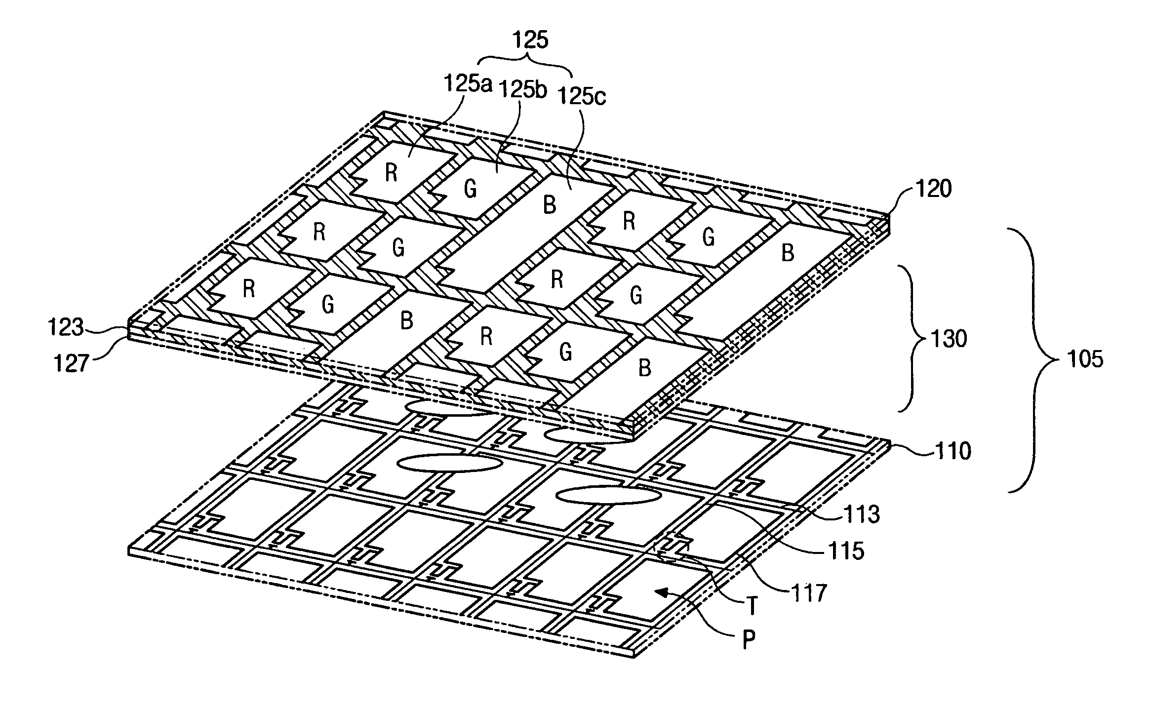
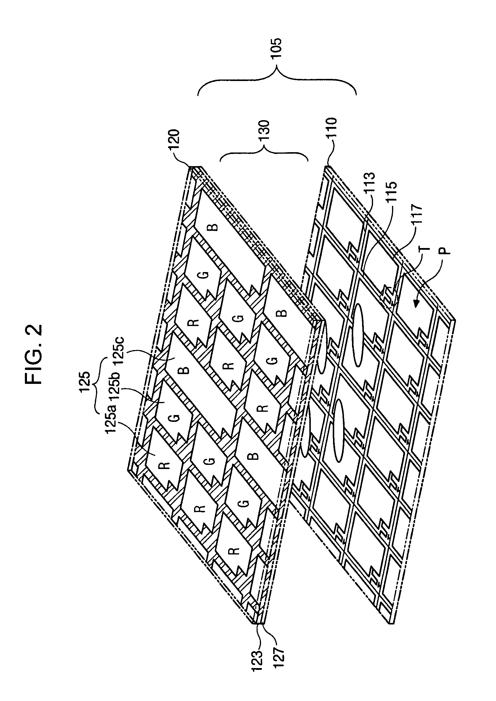
[0029]FIG. 2 is an expanded perspective view of a liquid crystal display (LCD) device according to the present invention. In FIG. 2, a liquid crystal display (LCD) device includes first and second substrates 110 and 120, which are spaced apart from and facing into each other, and a liquid crystal layer 130 interposed between the first substrate 110 and the second substrate 120.

[0030]A plurality of gate lines 113 and a plurality of data lines 115 are formed on the inner surface of the first substrate 110. The plurality of gate lines 113 and the plurality of data lines 115 cross each other to define sub-pixel regions P having a matrix form. A thin film transistor T is formed at each intersection of the gate li...


PUM


Abstract

A liquid crystal display device including a color filter is disclosed in the present invention. The liquid crystal display device includes a first substrate where a plurality of sub-pixels are defined thereon, a second substrate spaced apart from the first substrate, and a color filter layer on the second substrate, facing into the first substrate, and having a red sub-color filter, a green sub-color filter, and a blue sub-color filter, wherein one blue sub-color filter corresponds to two sub-pixels adjacent to each other in a first direction perpendicular to a second direction where the red, green, and blue sub-color filters are alternately located.

Description

[0001]This application claims the benefit of the Korean Patent Application No. P2002-088481 filed on Dec. 31, 2002, which is hereby incorporated by reference.BACKGROUND OF THE INVENTION[0002]1. Field of the Invention[0003]The present invention relates to a liquid crystal display device, and more particularly, to an active matrix liquid crystal display device including color filters of red, green, and blue. Although the present invention is suitable for a wide scope of applications, it is particularly suitable for reproducing images having near natural colors.[0004]2. Discussion of the Related Art[0005]In general, a liquid crystal display (LCD) device includes two substrates that are spaced apart from and face into each other, and a liquid crystal material layer interposed between the two substrates. Each of the substrates includes electrodes that face into each other, wherein a voltage applied to each electrode induces an electric field between the electrodes. An alignment of liquid...

Claims


Application Information

Patent Timeline
IPC IPC(8): G02F1/1335G09G3/36
CPCG02F1/133514G02F2201/52G02F1/1335
Inventor PARK, KWANG-SOONKIM, PYUNG-HUN
Owner LG DISPLAY CO LTD
Why Eureka
Try Eureka