
Automated image appearance control method

Active Publication Date: 2007-07-03
EASTMAN KODAK CO
View PDF8 Cites 6 Cited by
  • Summary
  • Abstract
  • Description
  • Claims
  • Application Information

AI Technical Summary

Benefits of technology

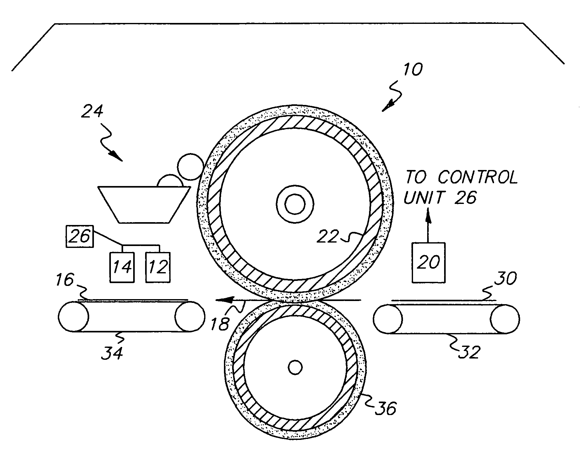
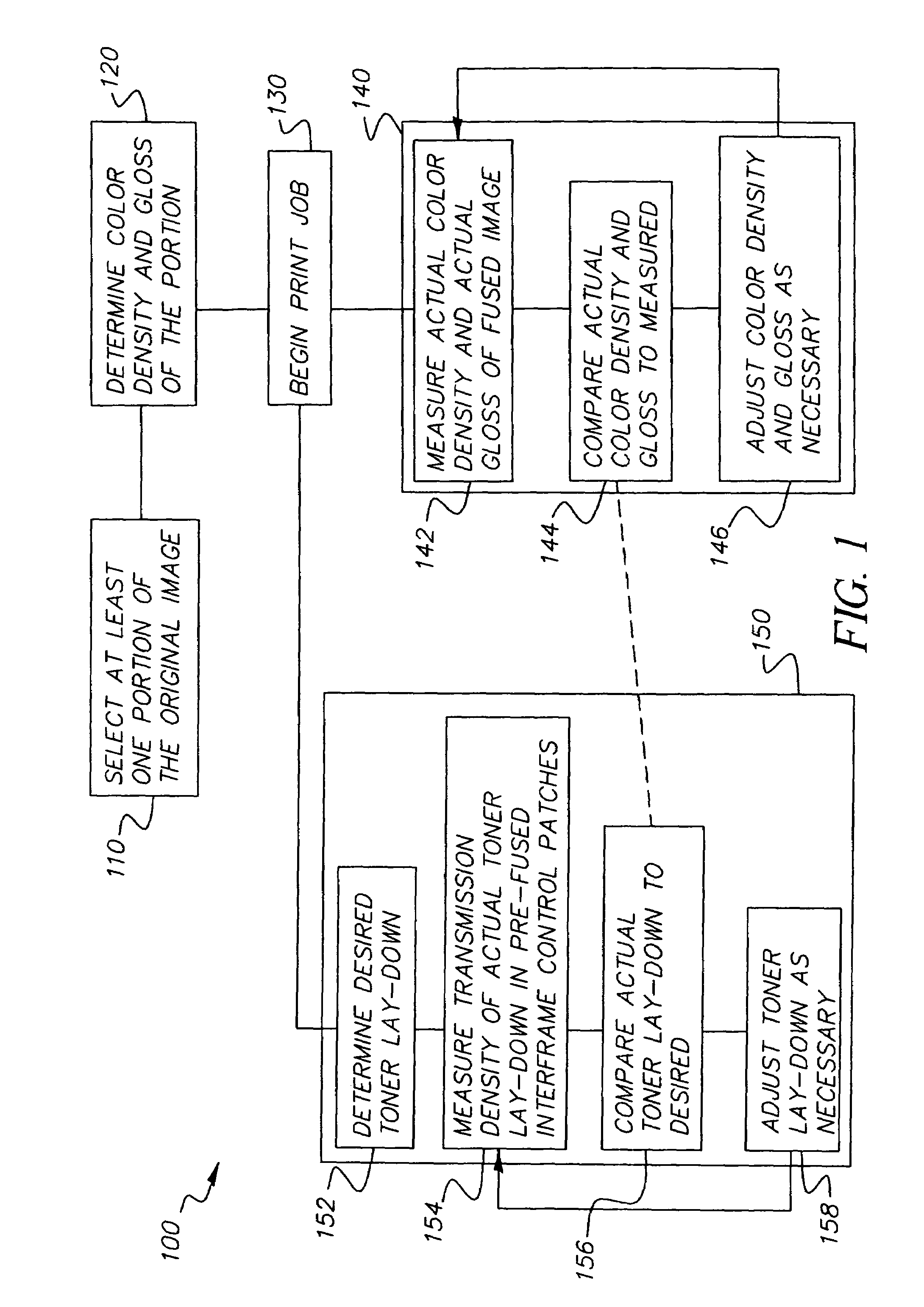
The present invention provides a method and device for controlling the appearance of a printed image on a media substrate by measuring the color density and gloss of the image and adjusting the appearance to match a predetermined value. This allows for better control over the appearance of printed images, improving quality control during a printing run and without requiring a calibration sheet. The method includes predicting the gloss and color density of the image based on a digital bit map of the image and the media substrate, measuring the actual color density and gloss of the image, and comparing it with the predicted value. The device includes a control unit and color densitometer for adjusting the appearance of the printed image.

Problems solved by technology

However, test sheets (i.e., calibration sheets), that are required to be sent to a proof tray, are considered as waste sheets.

Method used


Image

  • Automated image appearance control method
  • Automated image appearance control method
  • Automated image appearance control method

Examples


examples

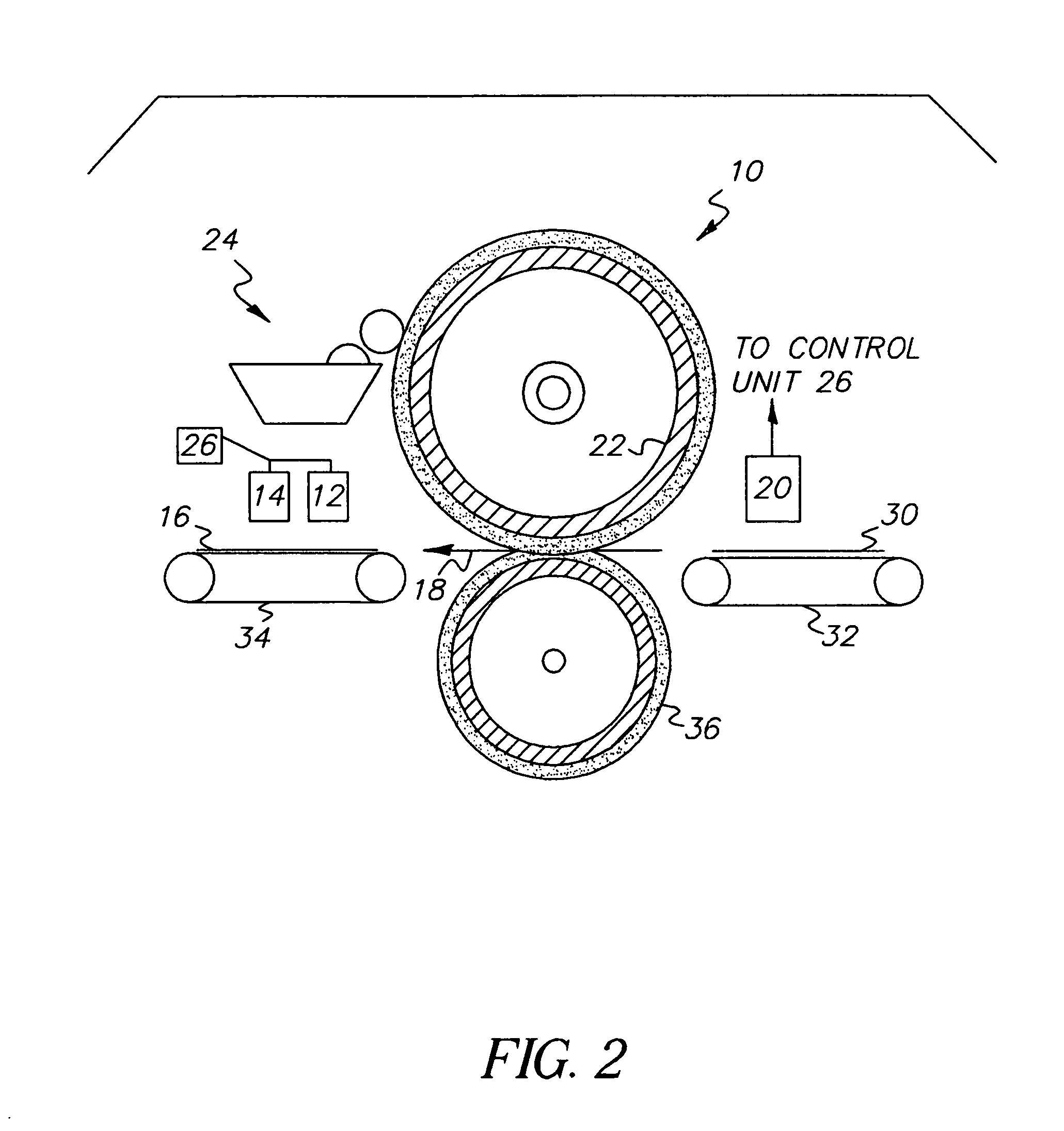
[0035]In one example of the present invention, one of the color separation densities, such as that for cyan, may be low (˜0.1 density off from Cyan Dmax), and the gloss sensitivity of the four-color 280% black may also be low. The gloss value of the red (yellow and magenta), yellow, magenta, and black may also be used to determine whether the overall gloss setting is correct. If the gloss setting is correct, but cyan density is low, then only the cyan density may need to be adjusted upward. There is no need to change the fuser nip to change the gloss value. Further confirmation of this low cyan density may come from supplemental transmission density measurements of the pre-fused image as measured by transmission densitometer 20.

[0036]In the above example, however, the overall gloss value for all the patches may show an indication of gloss change from its preset value (for example, all the Dmax and high toner coverage (above about 150% toner coverage) patches gloss are lowered), but ...


PUM


Abstract

An input image capture device, capable of sampling the color density and gloss of the fused printed image (thus not requiring the printing of density patches on a separate calibration page), may compare the printed image's color density and gloss to a predicted value. Then, appearance control may be achieved by changing fuser parameters (such as fuser nip width, fuser roller temperature and the like) and other electrophotographic element control parameters (such as exposure, off-set development voltage, charger voltage and the like) to maintain a desirable constant appearance (density, gloss, etc.) of images consistently in print engine usage (within a print run and between print runs), even if different media substrates are used on the same print job. Therefore, no waste calibration sheet is needed, and a print job operator may receive more timely feedback relating to the current printing job stream.

Description

CROSS REFERENCE TO RELATED APPLICATION[0001]Reference is made to and priority claimed from U.S. Provisional Application Ser. No. 60 / 532,161, filed Dec. 23, 2003, entitled IN-LINE APPEARANCE CONTROL METHOD.FIELD OF THE INVENTION[0002]The present invention generally relates to controlling in-line appearance of a reproduced image and, more specifically, to timely controlling the color density and gloss of a reproduced image while minimizing waste.BACKGROUND OF THE INVENTION[0003]In high-speed, high-quality electrophotographic printing applications, there are interactions between density (i.e., color gamut) and gloss of the fused images. Moreover, there is a strong influence on the final appearance of the print (i.e., overall gloss, differential gloss) based on the type of media substrate used. In some cases, as shown in U.S. Pat. No. 5,234,783, issued to Ng, the image appearance can also be modified with the addition of a transparent toner overcoat in selected areas.[0004]In a typical ...

Claims


Application Information

Patent Timeline
Patent Type & Authority Patents(United States)
IPC IPC(8): G03G15/00G03G15/01
CPCG03G15/01G03G15/5062G03G2215/0164
Inventor NG, YEE S.
Owner EASTMAN KODAK CO
Learn More