Vehicle hood assembly

a technology for hood assemblies and vehicles, applied in vehicle components, superstructure subunits, transportation and packaging, etc., can solve the problems of adding material and labor costs to the hood assembly, high cost of bonding fixtures and adhesives, etc., and achieves the effect of increasing structural support and increasing manufacturing eas

Active Publication Date: 2007-07-10
CK TECH
View PDF9 Cites 27 Cited by
  • Summary
  • Abstract
  • Description
  • Claims
  • Application Information

AI Technical Summary

Benefits of technology

[0006]The aforementioned problems are overcome by the present invention wherein a vehicle hood assembly is provided with a pair of fender panels that 1) provide increased structural support; 2) increase the ease of manufacture, and 3) provide integral air channels.
[0007]In a preferred embodiment, each fender panel attaches to the hood panel at a first attachment point and a second attachment point. Instead of the conventional small overlap at the attachment point, the fender panels of the present invention attach at a first point inwards of the lateral edge of the hood panel, and at a second point near the lateral edge of the hood panel. The multiple attachment points and resulting extra material in the fender panel between the attachment points increases the strength of the hood, and reduces the need for additional structural members.
[0008]In a more preferred embodiment, the fender panel is L-shaped in the section between the first attachment point and the second attachment point, forming a box shaped cross section between the hood panel and the fender panel. In another preferred embodiment, the L-shaped section of the fender panel is stepped in a number of locations. The steps further increase the structural strength of the vehicle hood. An additional result of this L-shaped section is that it forms a chamber between the fender panel and the hood panel that functions to channel outside air.
[0009]It is also preferable that the hood panel and the fender panels are injection molded plastic. The panels are separately molded into the desired shape, and then removably attached together at the attachment points. The use of plastic increases the ease of manufacture, and creates a much lighter vehicle hood, without reducing the structural integrity of the vehicle hood. The preferred attachment increases the ease of serviceability of a single panel.

Problems solved by technology

Unfortunately, the conventional assembly is difficult to separate for replacement of a panel, and the bonding fixtures and adhesive can be expensive.
The structural members and air channel are functional, but they add material and labor cost to the hood assembly.

Method used


Image

  • Vehicle hood assembly
  • Vehicle hood assembly
  • Vehicle hood assembly

Examples


Embodiment Construction

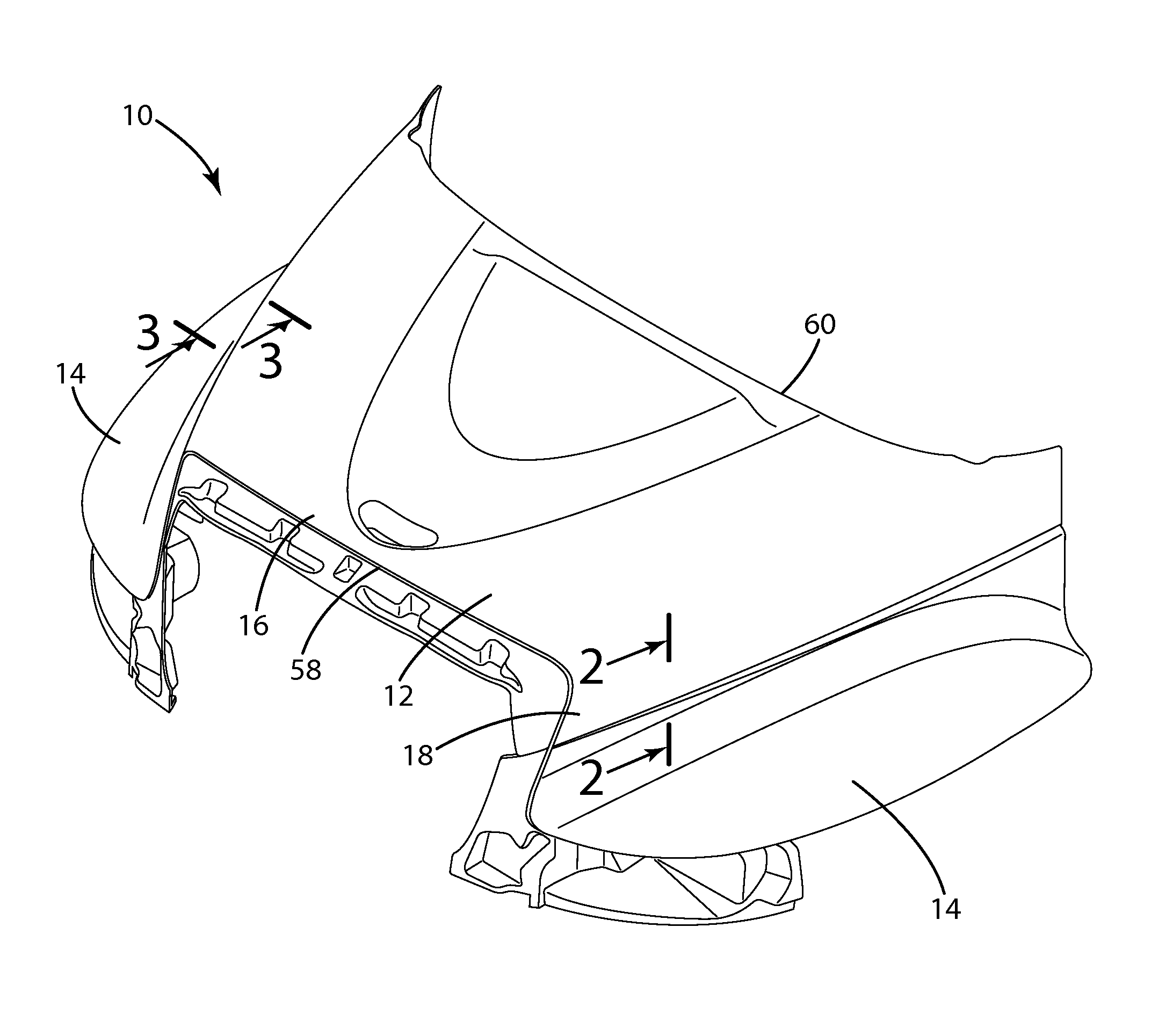
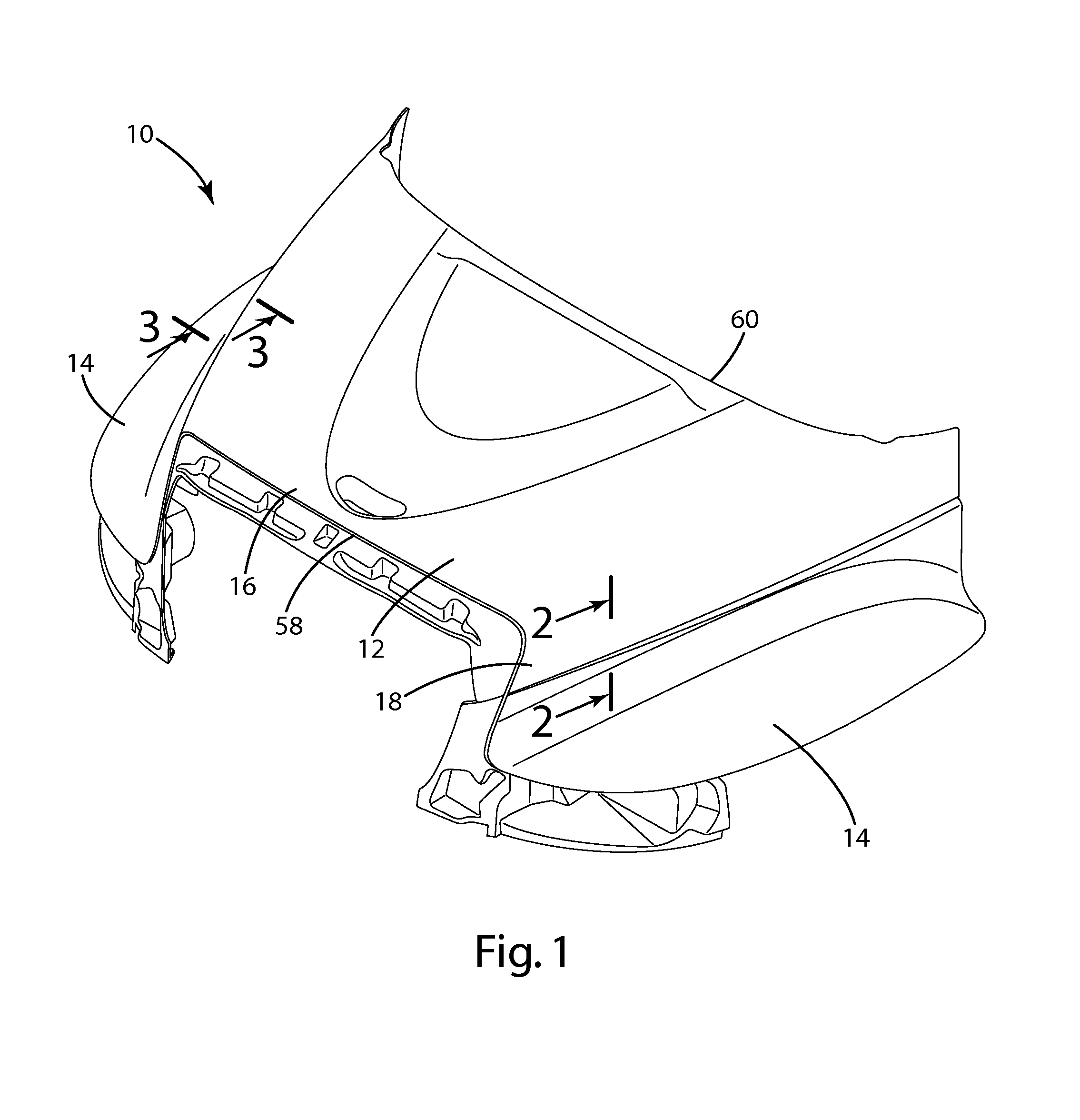
[0017]A vehicle hood in accordance with the preferred embodiment of the present invention is shown in FIG. 1 and generally designated 10. The vehicle hood 10 includes an injection molded hood panel 12, and a pair of injection molded fender panels 14 on opposing sides of the hood panel 12. The hood panel 12 includes a central portion 16 and opposing lateral portions 18 that extend downwardly from the central portion 16. Referring now to FIG. 4, the fender panels 14 are each attached to the hood panel 12 at a first attachment location 20 in the central portion 16 and a second attachment location 22 in the lateral portion 18. A chamber 24 is formed between the hood panel 12 and the fender panels 14 between the first and second attachment locations 20, 22. The vehicle hood is manufactured by injection molding the hood panel 12 and the fender panels 18, and then attaching the fender panels 18 to opposing sides of the hood panel 12.

[0018]The hood panel 12 is preferably molded as a single ...


PUM


Abstract

A vehicle hood assembly is provided with a pair of fender panels that attach to a central panel at a first attachment point and a second attachment point. The fender panel is L-shaped in cross-section between the first attachment point and the second attachment point such that it functions as an air management channel. The central panel and the fender panels are preferably injection molded parts. The present invention also includes a method for manufacturing a vehicle hood.

Description

BACKGROUND OF THE INVENTION[0001]The present invention is related to vehicle hood assemblies, and more particularly to a structurally improved vehicle hood assembly.[0002]Vehicle hood assemblies, especially those for trucks and other heavy duty vehicles, are generally comprised of sheet molding compound (“SMC”). These hoods may be comprised of a single piece, but are often comprised of multiple pieces, such as separate fender panels attached to a central hood panel. For example, FIG. 1 shows a multiple panel hood 10 having a generally horizontal hood panel 12, and a pair of fender panels 14 attached on either side of the hood panel 12.[0003]As shown in FIG. 2, fender panels 140 are commonly attached to the hood panel 120 with a small overlap 130 (approximately 2″) and a conventional bond, such as a two part adhesive. This conventional attachment provides an aesthetically pleasing seam 130 between the hood and the fender. Unfortunately, the conventional assembly is difficult to separ...

Claims


Application Information

Patent Timeline
Patent Type & Authority Patents(United States)
IPC IPC(8): B62D25/10B62D25/16
CPCB62D25/16
Inventor ELLERMAN, MICHAEL D.
Owner CK TECH
Why Eureka
Try Eureka