Dart with dual action arrangement

a dual-action arrangement and dart technology, applied in the field of darts, can solve the problems of severe damage to the accuracy of particular throwing, unstable entire dart, and vibration of the shaft and the dart housing, and achieve the effect of enhancing the stability of the dart when it is, and facilitating the removal of the dar

Inactive Publication Date: 2007-07-10
CHEN TE TSAO
View PDF8 Cites 5 Cited by
  • Summary
  • Abstract
  • Description
  • Claims
  • Application Information

AI Technical Summary

Benefits of technology

[0008]A main object of the present invention is to provide a dart comprising a dual action arrangement, which is capable of enhancing the stability of the dart when it is hit on a dart board, and of facilitating easy removal of the dart from that dart board.
[0009]Another object of the present invention is to provide a dart comprising the dual action arrangement, which is capable of restricting unnecessary relative movement between a shaft and a dart body while allowing the shaft to slidably move with respect to the dart body. In other words, although the shaft is allowed to slide for easy removal of the dart from a target, its overall stability will not be compromised.
[0010]Another object of the present invention is to provide a dart comprising the dual action arrangement, wherein the shaft is allowed to slide and rotate with respect to the dart body without affecting the overall stability of the dart.
[0011]Another object of the present invention is to provide a dart which does not involve complicated mechanical components so as to minimize the manufacturing cost of the present invention.

Problems solved by technology

A major problem for this conventional design of the dart is that since the shaft is allowed to have relative motion with respect to the dart housing, therefore, when the dart is hit on the target, the shaft and the dart housing may vibrate vigorously and the entire dart becomes very unstable.
The consequence may be that the accuracy of that particular throwing is severely undermined.
The key to the above problem is that there exists unpreventable relative movement of the shaft with respective to the dart body because the very reason for allowing the relative movement is to facilitate easy and convenient removal of the shaft from the target.
The problem with this technique is that when the relative movement between the shaft and the dart body is altogether eliminated, it is more difficult for the dart to be pulled out from the target.

Method used


Image

  • Dart with dual action arrangement
  • Dart with dual action arrangement
  • Dart with dual action arrangement

Examples


Embodiment Construction

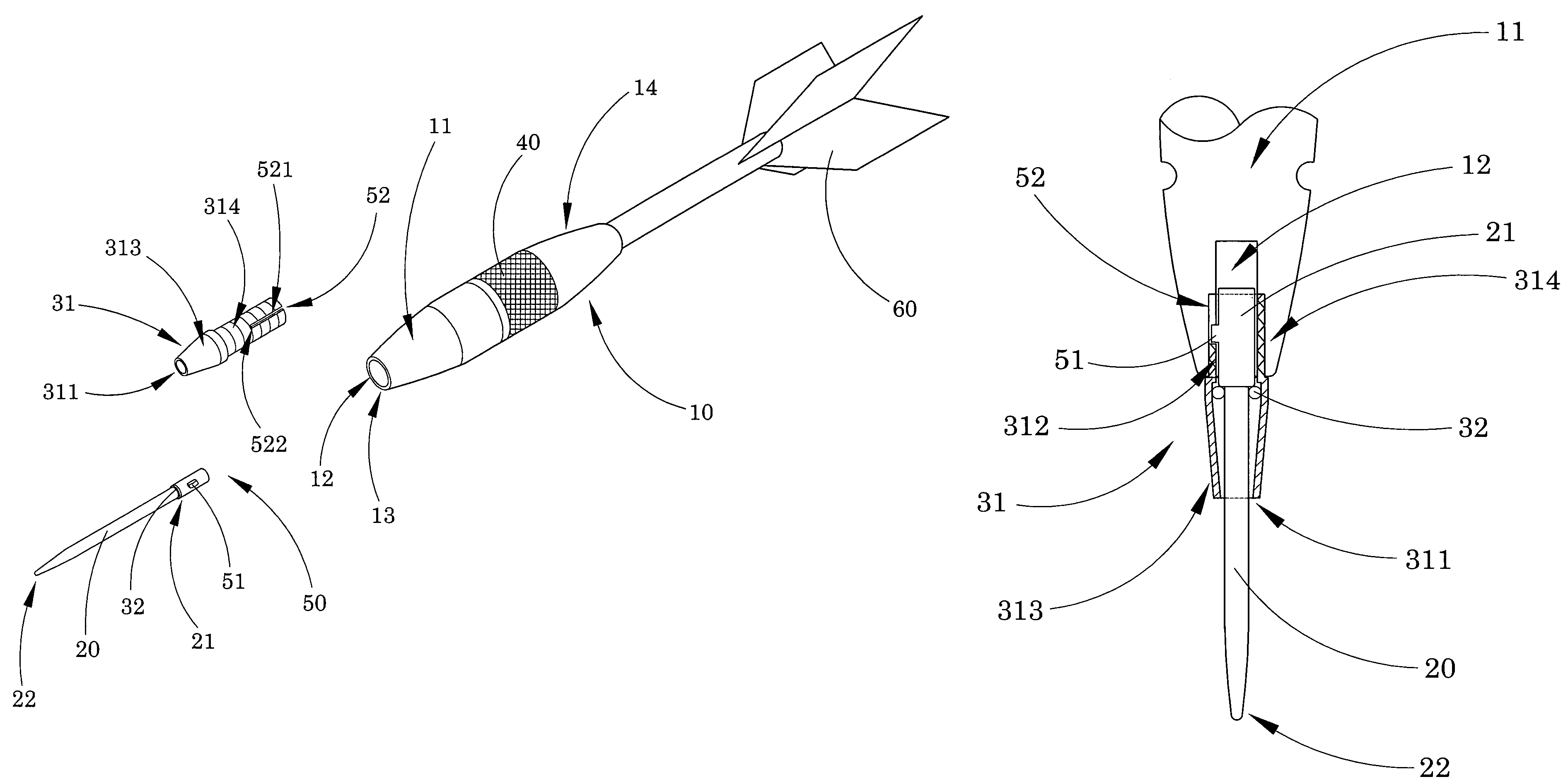
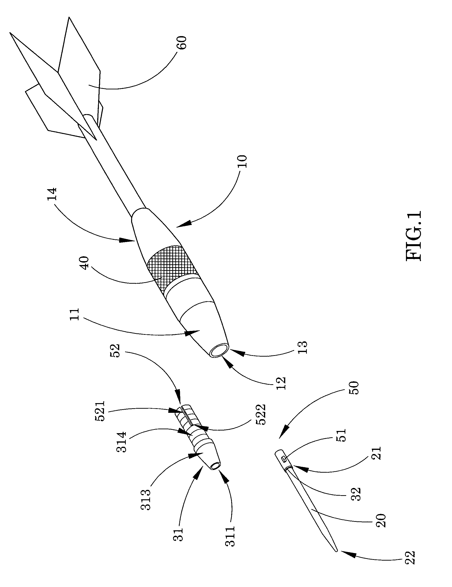
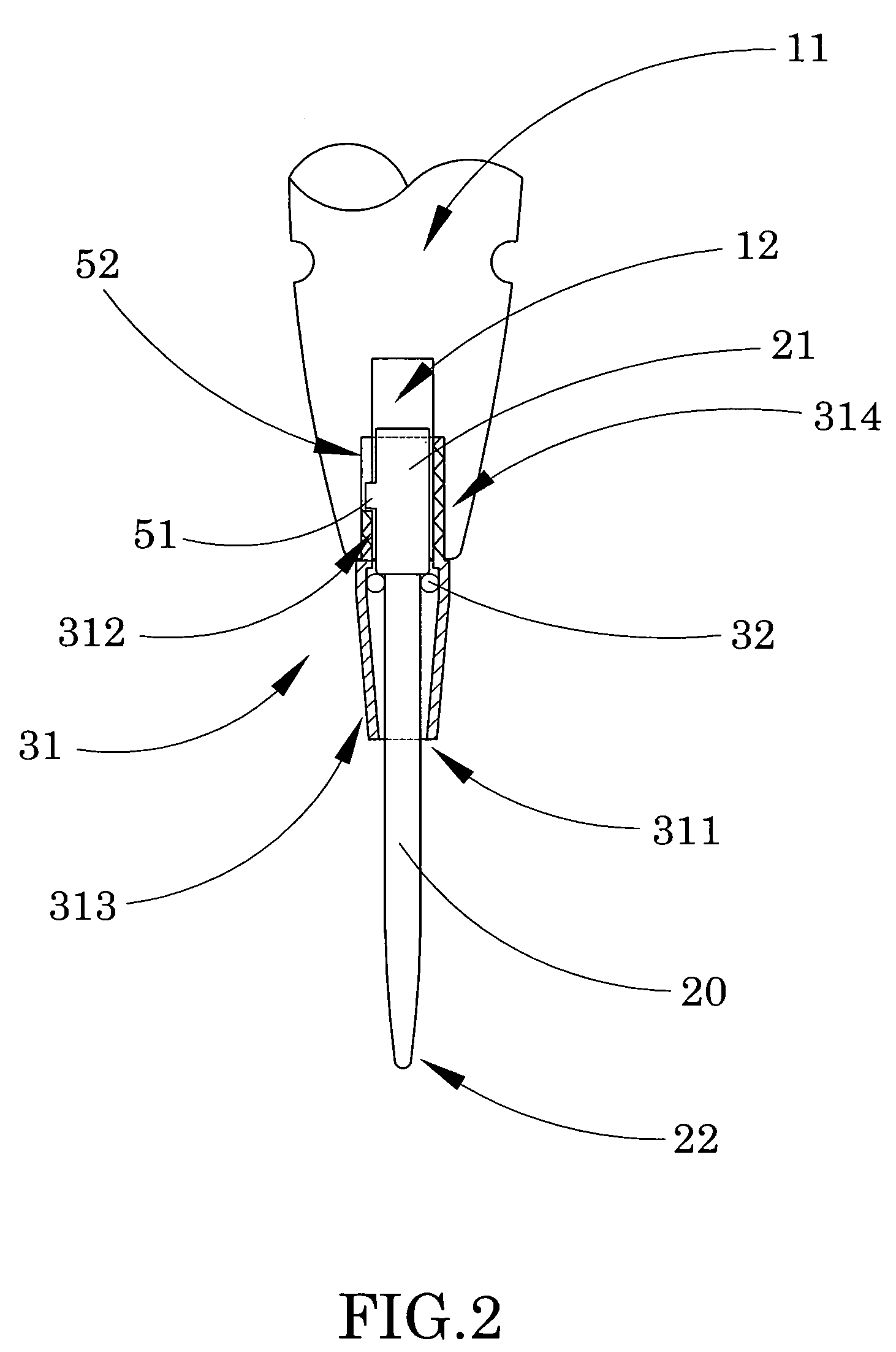
[0023]Referring to FIG. 1, FIG. 2 of the drawings, a dart according to a preferred embodiment of the present invention is illustrated, in which the dart comprises a dart barrel 10, a shaft 20, and a dual action arrangement.

[0024]The dart barrel 10 has a head portion 11 and a shaft channel 12 coaxially extending at the head portion 11, and defining a head opening 13 at the head portion 11 to communicate with the shaft channel 12. On the other hand, the shaft 20 has a sliding end portion 21 and a hitting tip 22.

[0025]The dual action arrangement comprises a tubular shaft housing 31 and a tubular elastic element 32, wherein the tubular shaft housing 31 is detachably mounted at the head opening 13 of the dart barrel 10, wherein the shaft housing 31 has a sliding slot 311 coaxially aligning with the shaft channel 12 for the sliding end portion 21 of the shaft 20 sliding therealong.

[0026]The tubular elastic element 32 is coaxially mounted at the sliding end portion 21 of the shaft 20 for a...


PUM


Abstract

A dart includes a dart barrel, a shaft having a sliding end portion, and a dual action arrangement. The dart barrel has a head portion and a shaft channel coaxially extending at the head portion, and defining a head opening at the head portion to communicate with the shaft channel. The dual action arrangement includes a tubular shaft housing detachably mounted at the head opening of the dart barrel, wherein the shaft housing has a sliding slot coaxially aligning with the shaft channel for the a sliding end portion of the shaft sliding therealong. The tubular elastic element is coaxially mounted at the sliding end portion of the shaft for applying an urging force against an inner circumferential wall of the sliding slot so as to minimize a clearance between the sliding slot and the sliding end portion of the shaft.

Description

BACKGROUND OF THE PRESENT INVENTION[0001]1. Field of Invention[0002]The present invention relates to a dart, and more particularly to a dart comprising a dual action arrangement which is capable of enhancing the stability of the dart when it is hit on a dart board, and of facilitating easy removal of the dart from that dart board.[0003]2. Description of Related Arts[0004]A conventional dart typically comprises a dart body having a tail portion and a head portion, a flyer mounted on the tail portion, a shaft housing mounted at the head portion of the dart body, and a shaft extended from the shaft housing for hitting on a target.[0005]As a matter of conventional arts, a typical shaft usually has a sharpened tip portion and a connecting portion slidably received in the shaft housing so that when the dart is inserted into the target (such as a dart board), it is easier and more convenient for the player to pull it out from the target. Moreover, it is usual for the shaft to be also rotat...

Claims


Application Information

Patent Timeline
Patent Type & Authority Patents(United States)
IPC IPC(8): A63B65/02
CPCF42B6/003
Inventor CHEN, TE-TSAO
Owner CHEN TE TSAO
Why Eureka
Try Eureka