Fastener driving tool

a technology of fastener and driving tool, which is applied in the field of fastener driving tool, can solve the problems of damage to the driver blade b>22/b>′, and achieve the effects of reducing local wear on the guide surface due to the contact of the nail head portion with the guide surface, ensuring the durability of the driver blade, and improving the durability of the guide surfa

Active Publication Date: 2007-07-17
KOKI HLDG CO LTD
View PDF12 Cites 10 Cited by
  • Summary
  • Abstract
  • Description
  • Claims
  • Application Information

AI Technical Summary

Benefits of technology

[0021]An object of the present invention is to provide a fastener driving tool capable of improving the durability of the guide surface and maintaining the durability of the free end surfaces of the driver blade by eliminating the drawbacks of a related art fastener driving tool and reducing the local wear on the guide surface ascribed to the contact of the nail head therewith.
[0023]According to the fastener driving tool of such a structure, the local wear on the guide surface due to the contact of the nail head portion with the guide surface can be reduced, this enabling a fastener driving tool capable of improving the durability of the guide surface to be provided.
[0024]Preferably, a diameter of the guide surface of the projection is set equal to a maximum diameter of the head portion of the nail to be used, so that the areas of the free end surfaces of the driver blade can be secured, this enabling the durability of the driver blade to be maintained.

Problems solved by technology

As a result, the areas of the free end surfaces become small to cause the driver blade 22′ to be damaged due to the wear on and the excessively large surface pressure on the guide surface.

Method used


Image

  • Fastener driving tool
  • Fastener driving tool
  • Fastener driving tool

Examples


Embodiment Construction

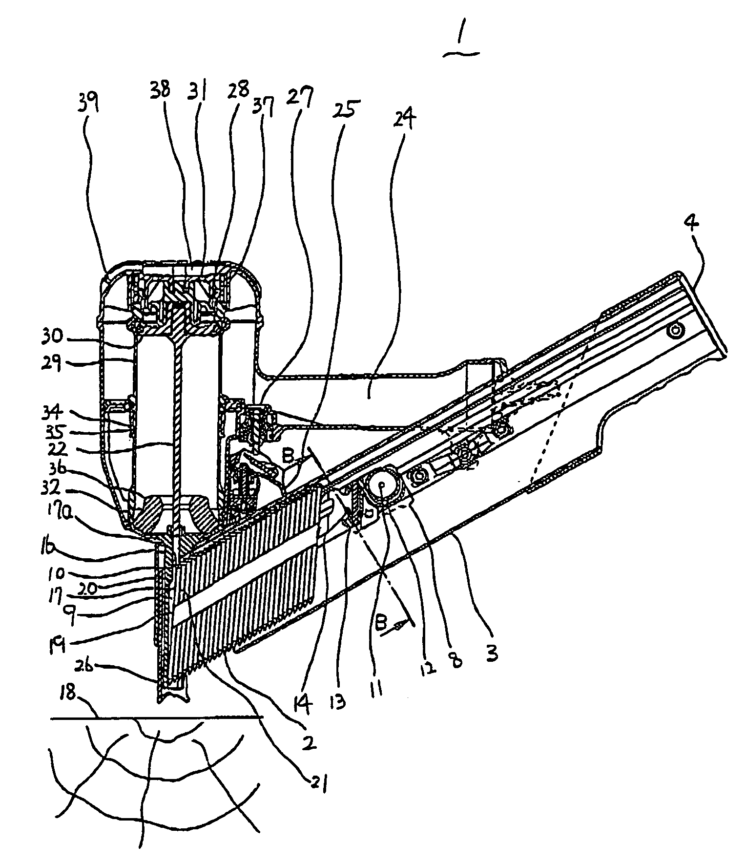
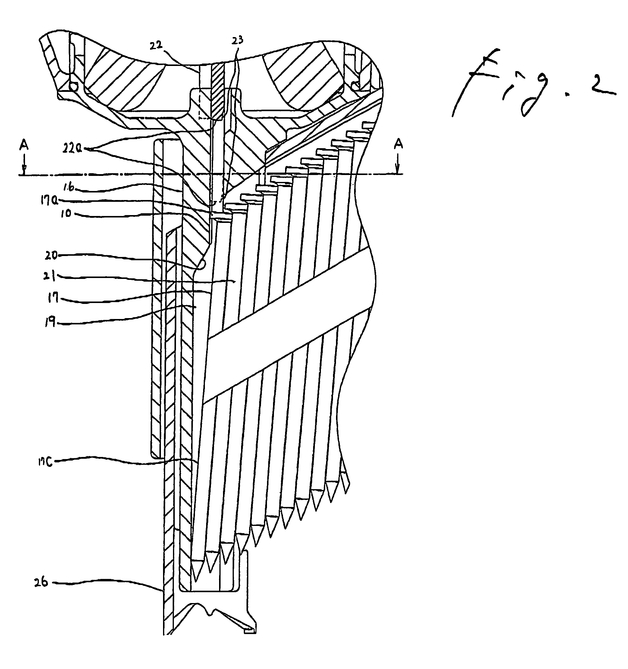
[0037]One embodiment of the guide surface 10 of the exit port 19 of the fastener driving tool according to the present invention will be described by using FIG. 1 to FIG. 5.

[0038]The diameter of the guide surface 10 in this mode of embodiment is set equal within the scope of the specification to a maximum diameter of a nail head 2a. In short, the outer circumferential surface of the nail head 2a contacts substantially the whole of the guide surface 10, so that a surface pressure applied to the guide surface 10 becomes small. This enables the local wear on the guide surface to decrease, and the durability of the guide surface 10 to be improved.

[0039]The areas of the free end surfaces 22a of the driver blade 22 are not different from those of the corresponding portions of the related art structure of FIG. 7 and FIG. 8, so that the durability of the driver blade can be maintained.

[0040]To be concrete, in this mode of embodiment, the diameter and width of the guide surface 10 are 7.1 mm...


PUM


Abstract

A fastener driving tool includes: a driver blade adapted to drive nails joined to one another into an object in order; a nose adapted to guide the driver blade and nails; and a guide surface of a projection adapted to guide a head portion of a first nail struck out into an exit hole of the nose so that the second nail is not exposed to the exit hole. The guide surface of the projection is formed to a shape identical with that of the head portions of the nails.

Description

BACKGROUND OF THE INVENTION[0001]1. Field of the Invention[0002]The present invention relates to a fastener driving tool provided with an improved nail head guide surface of an exit port from which nails are struck out.[0003]2. Background Art[0004]A related art fastener driving tool will be described by using FIGS. 6 to 10.[0005]The loading of nails 2, which are joined together substantially in parallel with one another at equal intervals by a connecting member made of paper, a plastic material and the like, into a magazine is done from a nail loading port opened in a rear end wall of the magazine 3.[0006]The shape of a cross section of the magazine 3 taken in the direction which is at right angles to the direction in which the nail 2 is supplied is as shown in FIG. 6, so as to retain the nail 2.[0007]In an upper portion of FIG. 6, an upper side of a nail head 2a is held on an upper surface 5a of a guide groove 5. In a lower portion of the same drawing, a lower side of the nail head...

Claims


Application Information

Patent Timeline
Patent Type & Authority Patents(United States)
IPC IPC(8): B25C1/04
CPCB25C1/188
Inventor ISHIZAWA, YOSHINORIKITAGAWA, HIROKINISHIDA, MASASHI
Owner KOKI HLDG CO LTD
Why Eureka
Try Eureka