Method and system for noise floor calibration and receive signal strength detection

a signal strength detection and noise floor technology, applied in the field of communication systems, can solve problems such as difficult circuit construction accuracy, difficult referring to the antenna, and significant gain variation between units

Inactive Publication Date: 2007-07-17
QUALCOMM INC
View PDF6 Cites 83 Cited by
  • Summary
  • Abstract
  • Description
  • Claims
  • Application Information

AI Technical Summary

Benefits of technology

[0022]The present invention provides a relative estimate of the power of the thermal noise floor of the receiver, equal to the thermal noise at the antenna plus the noise figure of the receiver's analog front end. The receive signal strength of incoming signals can then be determined relative to the measured noise floor, ret...

Problems solved by technology

Along with the difficulty of making an accurate signal power measurement at baseband, there are difficulties in referring the measurement to the antenna.
In addition, variation in the components used to match the RF circuits can cause significant variation in gain from one unit to another.
However, ...

Method used


Image

  • Method and system for noise floor calibration and receive signal strength detection
  • Method and system for noise floor calibration and receive signal strength detection
  • Method and system for noise floor calibration and receive signal strength detection

Examples


Embodiment Construction

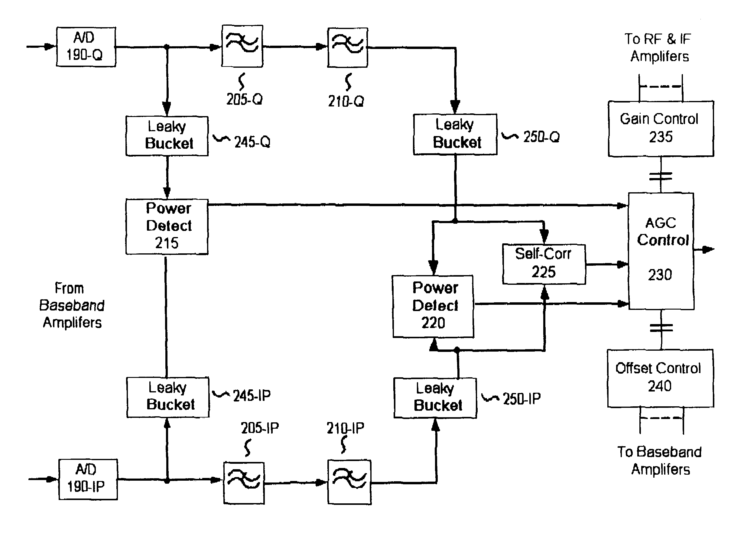
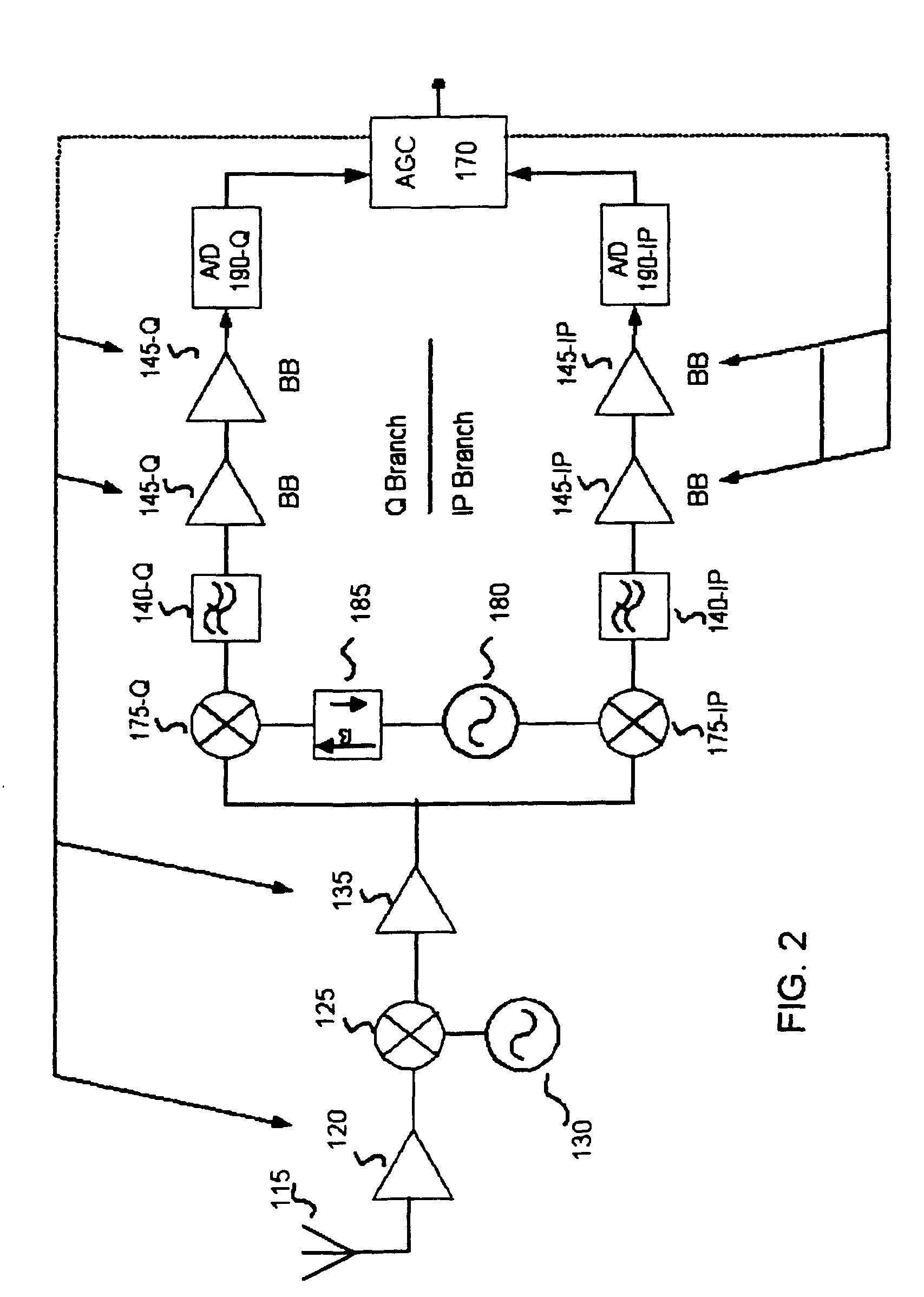
[0032]The basic structure of a receiver used in an embodiment of the present invention is shown in FIG. 2. Here, a wideband antenna 115 receives a radio frequency (RF) RF signal and provides it to an RF amplifier 120, and a particular channel or signal within the band is preferably selected by varying the local oscillators 130 and 180. In the embodiment, the RF signal preferably conforms to the IEEE 802.11a standard, has a frequency in the 5 to 6 GHz band and is quadrature modulated to carry 6 to 54 Mbps. In this embodiment, the signal can carry up to 54 Mbits of data or more and lies within one of twelve 20 MHz wide slots, eight within a 5.15-5.35 GHz band and four within a 5.75-5.85 GHz band. The signal in this embodiment is a coded orthogonal frequency division multiplexed (OFDM) signal using 52 subcarriers spaced 312.5 kHz apart. It is understood, however, that while the following detailed description is made in the context of an IEEE 802.11a system, the invention described here...


PUM


Abstract

A system for detecting the level of the noise floor due to circuit noise as seen at the ADC for a wireless receiver. The system measures power after digitizing and filtering, and subtracts off any variable gain used in the analog front end to determine differentially the size of the signal at the antenna. The system further differentially detects the signal size of any incoming signal at the antenna in a similar fashion, and determines its size relative to the measured noise floor. If the level of the circuit noise of the receiver is known absolutely, the absolute signal size of the incoming signal can likewise be determined with this inventive method and system.

Description

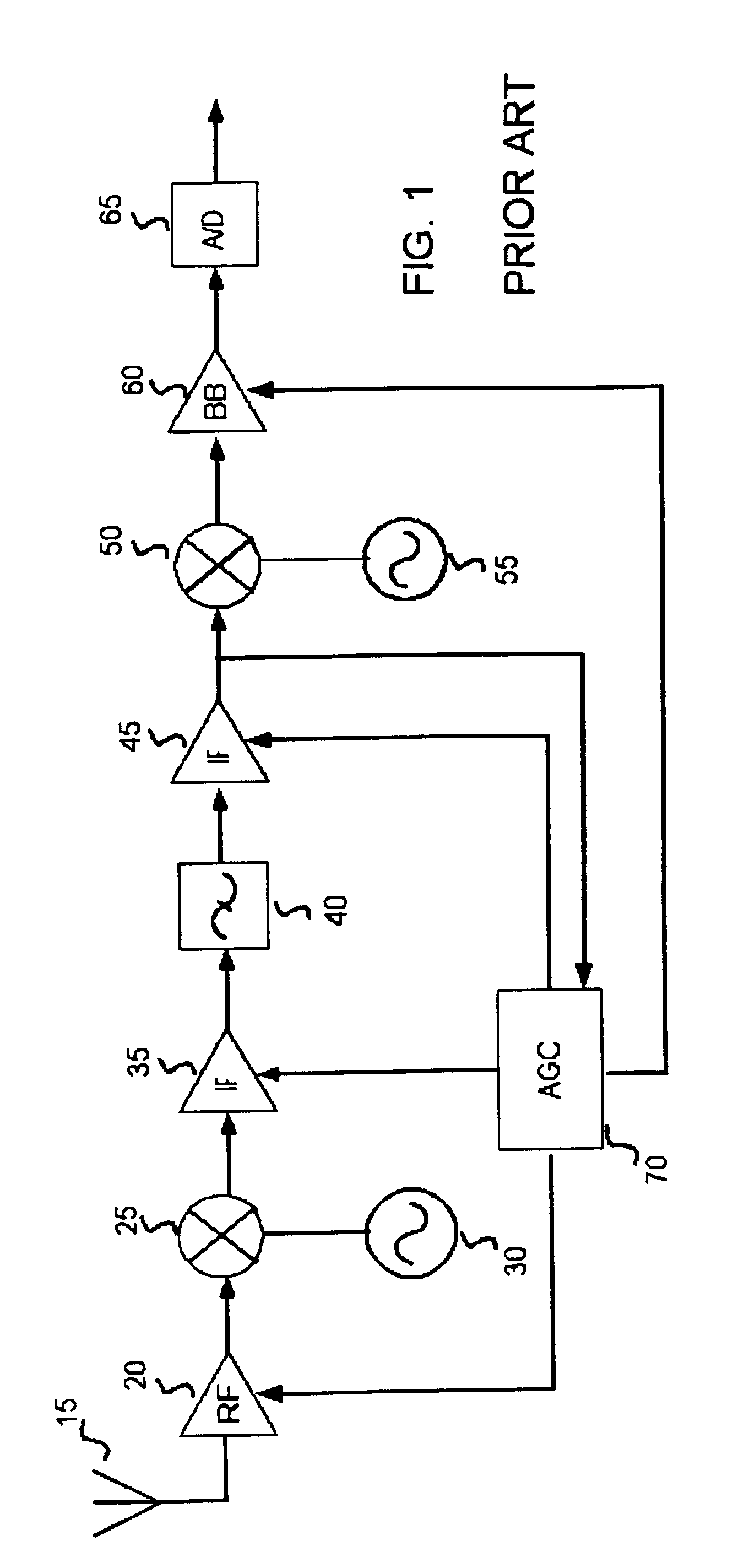
CLAIM OF PRIORITY[0001]This invention claims priority to the following co-pending U.S. provisional patent application, which is incorporated herein by reference, in its entirety:[0002]Husted et al, Provisional Application Ser. No. 60 / 325,024, entitled “METHOD AND SYSTEM FOR NOISE FLOOR CALIBRATION AND RECEIVE SIGNAL STRENGTH DETECTION,” filed, Sep. 25, 2001.BACKGROUND OF THE INVENTION[0003]1. Field of the Invention[0004]The present invention is directed to communication systems. More particularly, the invention is directed to receivers in wireless communication systems. Even more particularly, the present invention is directed to noise floor calibration and signal strength detection systems for such wireless communication system receivers.[0005]2. Background[0006]The use of receivers in wireless systems such as radio and cellular communication systems is well-known in the art. FIG. 1 shows a typical superheterodyne receiver design 10. Here, a radio frequency (RF) signal is received ...

Claims


Application Information

Patent Timeline
IPC IPC(8): H04B17/00
CPCH03G3/3068H04B17/345H03G3/3078
Inventor HUSTED, PAUL J.MCFARLAND, WILLIAM J.
Owner QUALCOMM INC
Why Eureka
Try Eureka