Radio receiver and radio signal processing method with controlling gain

a radio receiver and gain technology, applied in the direction of gain control, transmission monitoring, digital transmission, etc., can solve problems such as degrading reception performance, and achieve the effect of degrading reception performan

Inactive Publication Date: 2007-07-17
KK TOSHIBA
View PDF17 Cites 67 Cited by
  • Summary
  • Abstract
  • Description
  • Claims
  • Application Information

AI Technical Summary

Benefits of technology

[0011]An advantage of an aspect of the present invention is to provide a radio receiver of direct conversion scheme in which degradation of the reception performance caused by the transient response component of the DC offset is suppressed.

Problems solved by technology

In some cases, therefore, DC offsets of both the LNA 20 and the VGA 50 overlap each other, and a very large transient response component occurs, resulting in a degraded reception performance.

Method used


Image

  • Radio receiver and radio signal processing method with controlling gain
  • Radio receiver and radio signal processing method with controlling gain
  • Radio receiver and radio signal processing method with controlling gain

Examples


Embodiment Construction

[0025]Hereafter, embodiments according to the present invention will be described with reference to the drawings. These embodiments do not restrain the present invention. In a radio receiver of a direct conversion scheme according to embodiments of the present invention, the gain of the LNA and the gain of the VGA can be changed respectively at points in time that are different from each other. As a result, the transient response component of the DC offset in the output of the VGA is reduced.

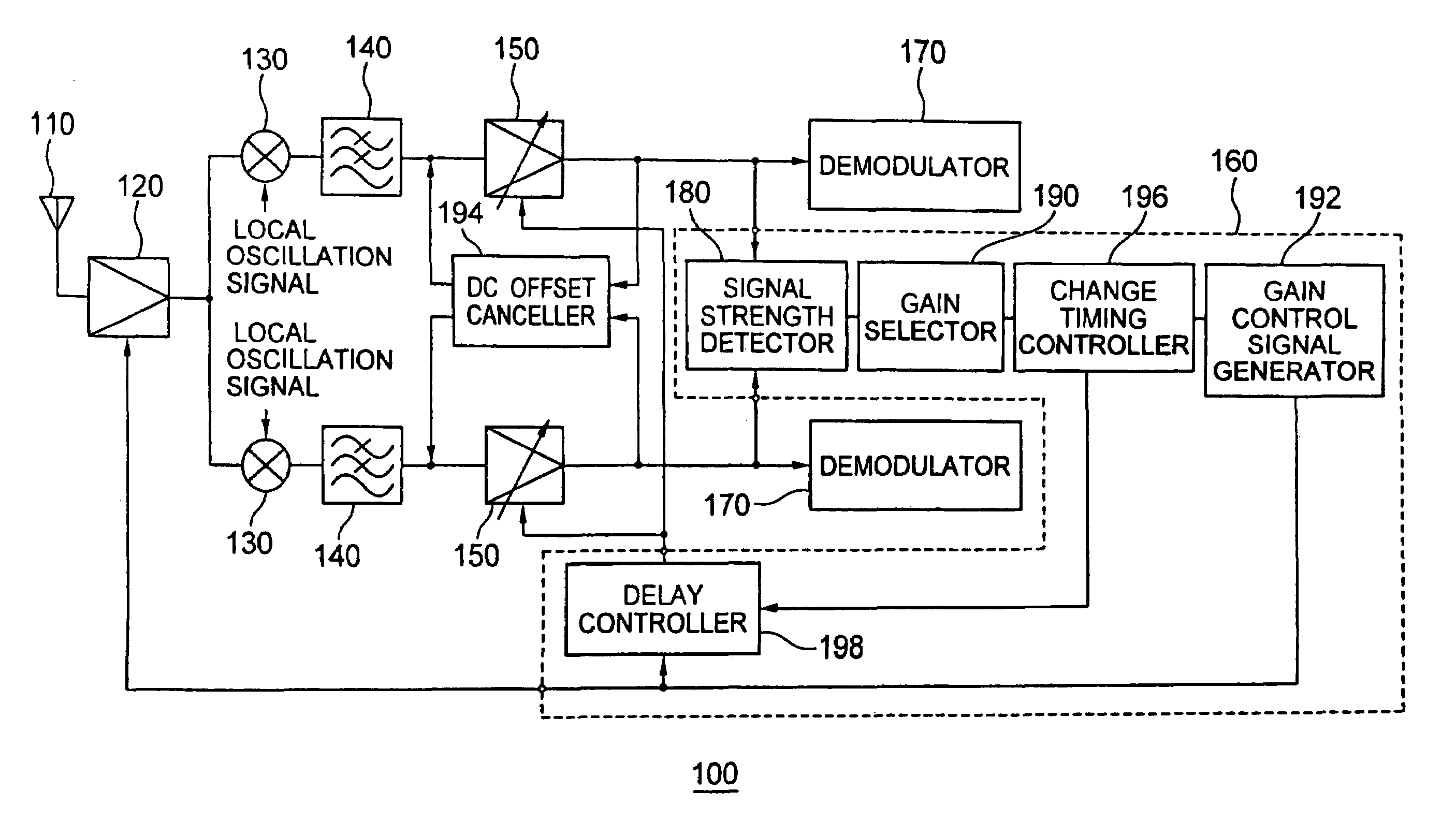
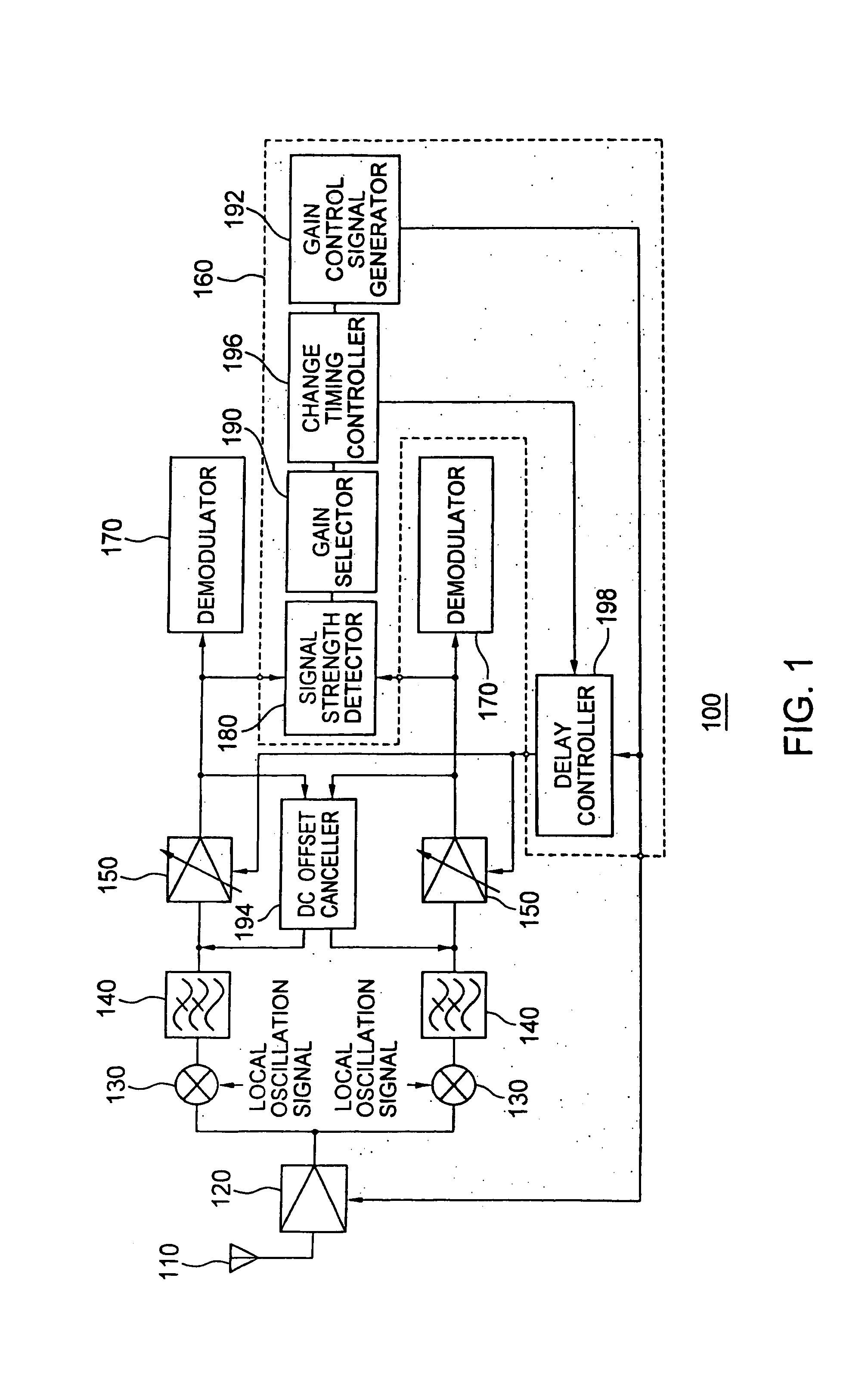
[0026]FIG. 1 is a block diagram of a radio receiver 100 according to an embodiment of the present invention. The radio receiver 100 is a radio receiver using the direct conversion scheme. The direct conversion scheme is a scheme in which an RF signal having a high frequency is converted to a baseband signal having a low frequency without using an intermediate frequency. The radio receiver 100 includes an antenna 110, an LNA 120, a quadrature demodulator 130, an LPF 140, a VGA 150, a gain control...


PUM


Abstract

A radio receiver comprises a first amplifier to amplify a received radio signal; a quadrature demodulator to demodulate the radio signal amplified by said first amplifier and thereby generate a baseband signal; a second amplifier to amplify the baseband signal; a demodulator to demodulate the baseband signal amplified by said second amplifier; and a gain controller to control timing of a change in a gain of said second amplifier, in case that changing the gain of said first amplifier and the gain of said second amplifier, on the basis of a gain of said first amplifier before and after the change.

Description

CROSS-REFERENCE TO RELATED APPLICATION[0001]This application is based upon and claims the benefit of priority from the prior Japanese Patent Application No. 2003-122316, filed on Apr. 25, 2003, the entire contents of which are incorporated herein by reference.BACKGROUND OF THE INVENTION[0002]1. Field of the Invention[0003]The present invention relates to a radio receiver and a radio signal processing method.[0004]2. Related Background Art[0005]In recent years, radio communication devices have widely spread. As a result, it is increasingly demanded to reduce the number of components and the manufacture cost for a radio circuit and manufacture the radio circuit as a monolithic IC. In order to cope with this demand, the direct conversion scheme is adopted for the radio circuits.[0006]FIG. 8 is a block diagram of a conventional receiver adopting the direct conversion scheme. An antenna 10 receives an RF (Radio Frequency) signal, and an LNA (Low Noise Amplifier) 20 amplifies this RF sign...

Claims


Application Information

Patent Timeline
Patent Type & Authority Patents(United States)
IPC IPC(8): H04B1/06H03G3/20H03D3/00H03G3/30H04B1/10H04B1/16H04B1/30H04L27/38
CPCH03D3/008H03G3/3068H04B1/30H04L27/3809H04B1/10
Inventor SEKIGUCHI, TAKAHIROYOSHIDA, HIROSHISETO, ICHIROTOYODA, TAKEHIKO
Owner KK TOSHIBA
Why Eureka
Try Eureka