Railway system with at least one track, and method for encoding data for transmission over the track

a technology of digital encoding and transmission system, which is applied in the direction of vehicle position/course/altitude control, process and machine control, instruments, etc., can solve the problems of relatively small encoding capacity and shortcomings of conventional methods, so as to improve increase the encoding capacity, increase the safety of the system and method, when receiving and/or interpreting the signal

Inactive Publication Date: 2007-07-17
SIEMENS AG
View PDF4 Cites 2 Cited by
  • Summary
  • Abstract
  • Description
  • Claims
  • Application Information

AI Technical Summary

Benefits of technology

[0010]According to another feature of the present invention, the encoding capacity can be increased if the logical signal states can assume logical states 1; 0.33; −0.33; or −1.
[0011]According to another feature of the present invention, the safety of the system and method, when receiving and / or interpreting the signal, can be increased if the electrical signals include an identifying pulse having a negative or a positive polarity, regardless of a polarity of a following signal. In other words, the following signal values can have either a negative or a positive polarity. The identification pulse need not be the first signal value in a time interval, but can be any other predetermined signal value, for example the second or third signal value. The polarity should be a selected so that the DC component is reduced, for example, to a value close to zero.
[0012]The safety of the system can be further improved by using the level of the first signal value as a reference signal. The reference signal can correspond to the logical signal state +1, but may also correspond to a logical signal state −1.

Problems solved by technology

Heretofore, conventional methods suffer shortcomings as data encoding has a relatively small encoding capacity.

Method used


Image

  • Railway system with at least one track, and method for encoding data for transmission over the track
  • Railway system with at least one track, and method for encoding data for transmission over the track
  • Railway system with at least one track, and method for encoding data for transmission over the track

Examples


Embodiment Construction

[0018]Throughout all the Figures, same or corresponding elements are generally indicated by same reference numerals. These depicted embodiments are to be understood as illustrative of the invention and not as limiting in any way. It should also be understood that the drawings are not necessarily to scale and that the embodiments are sometimes illustrated by graphic symbols, phantom lines, diagrammatic representations and fragmentary views. In certain instances, details which are not necessary for an understanding of the present invention or which render other details difficult to perceive may have been omitted.

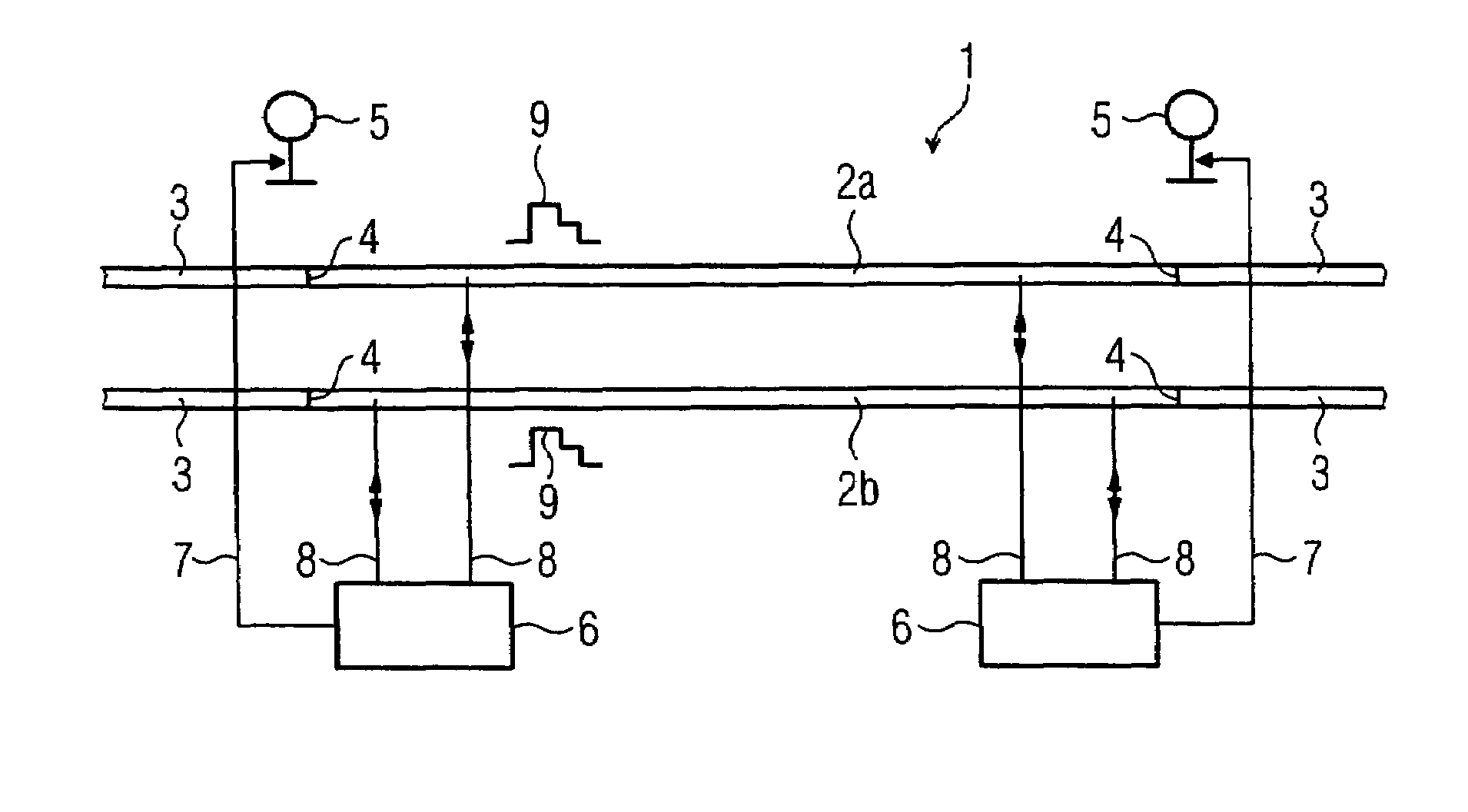
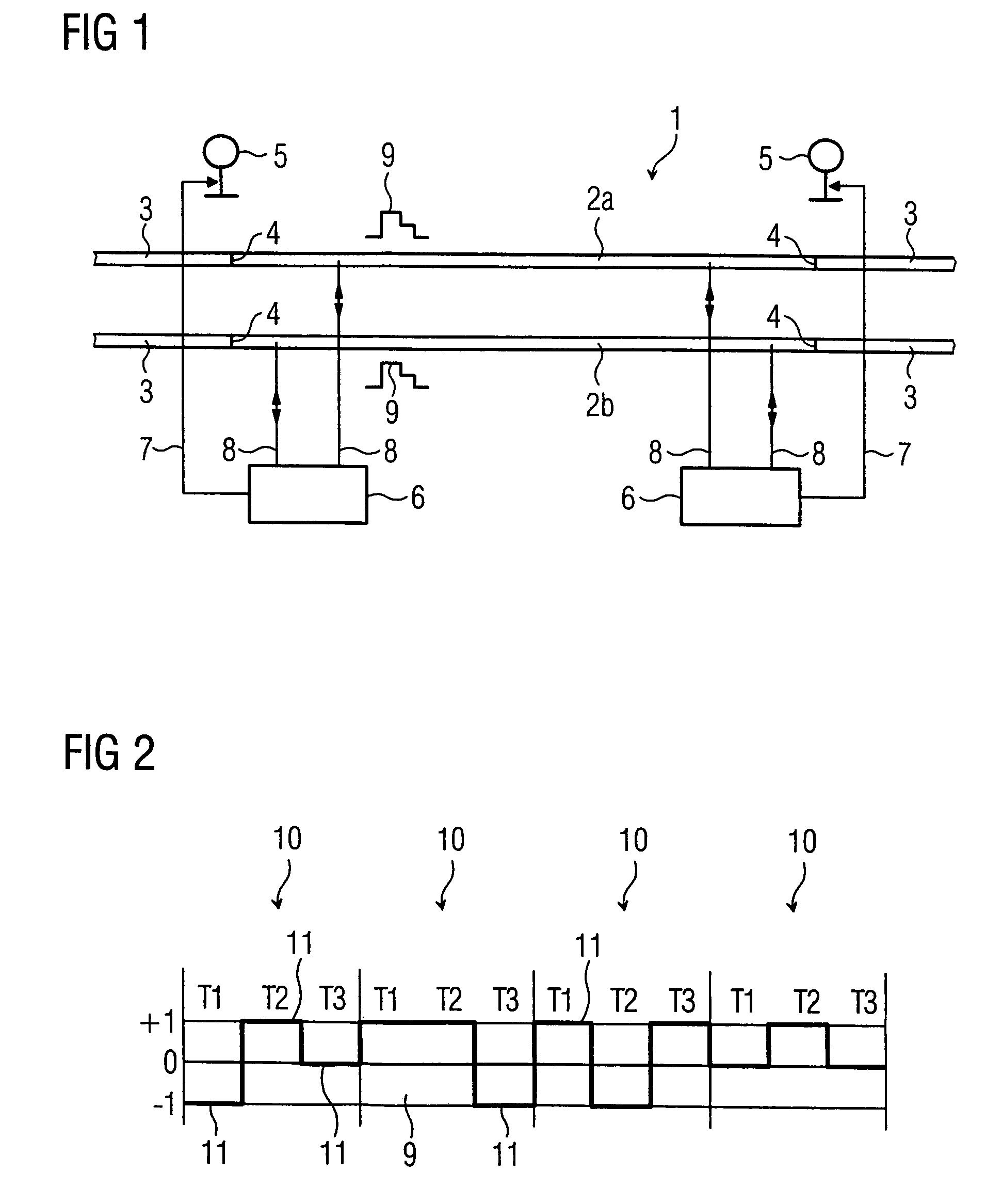
[0019]Turning now to the drawing, and in particular to FIG. 1, there is shown a schematic illustration of a railway system according to the present invention, including a track section 1 which is comprised of two rails 2a, 2b. The two rails 2a, 2b of track section 1 are electrically insulated from rails 3 of the continuous track by insulators 4 (insulation joints). Disposed in...


PUM


Abstract

A railway system with at least one track having at least two rails and a method for encoding data for this railway system are disclosed. Railway signaling systems are located proximate to the tract for controlling railway cars moving along the rails. The railway system also includes safety systems associated with the railway signaling systems for exchanging data between the safety systems for safely controlling the railway signaling systems. The data are exchanged bidirectionally by signal pulses, whereby digital electrical signals are transmitted via the two electrically conducting rails. For encoding the data, each data point is formed from one or more signal pulses within a predetermined cycle time which is divided into time intervals. The encoding capacity can be enhanced, without significantly increasing the complexity, by using electrical signals that contain the encoded data in each time interval in form of at least one of three different signal states.

Description

CROSS-REFERENCES TO RELATED APPLICATIONS[0001]This application claims the priority of German Patent Application, Serial No. 10 2005 036 498.5, filed Jul. 28, 2005, pursuant to 35 U.S.C. 119(a)–(d), the subject matter of which is / are incorporated herein by reference.BACKGROUND OF THE INVENTION[0002]The present invention relates to a railway system with at least one track, and to a method for digital encoding of data for bidirectional transmission over the track.[0003]Nothing in the following discussion of the state of the art is to be construed as an admission of prior art.[0004]Railway systems that detect the presence of track-bound vehicles on a track are known. The tracks are typically comprised of two rails, with the vehicles' wheels and axles that span the rails acting as a shunt between the rails. Railway signals for controlling movement of the railway cars are typically arranged proximate to the tracks. Safety devices are associated with the railway signals and exchange data o...

Claims


Application Information

Patent Timeline
Patent Type & Authority Patents(United States)
IPC IPC(8): G05D1/00B61L21/00
CPCB61L27/0005B61L27/70
Inventor WILMS, GERHARD
Owner SIEMENS AG
Why Eureka
Try Eureka