Self-moving vacuum cleaner with moveable intake nozzle

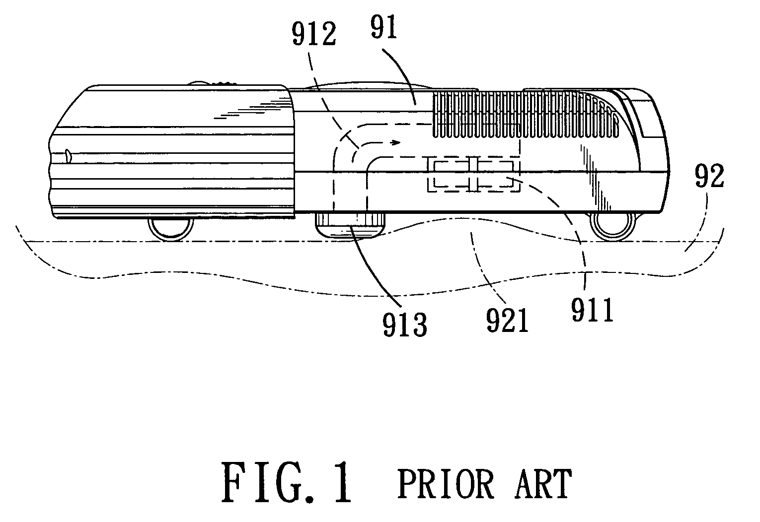
a vacuum cleaner and intake nozzle technology, which is applied in the direction of cleaning equipment, instruments, optical elements, etc., can solve the problems of cleaners becoming stuck during cleaning operation, deteriorating cleaning performance of cleaners,

Active Publication Date: 2007-07-24
HUNAN GRAND PRO ROBOT TECH
View PDF8 Cites 159 Cited by
  • Summary
  • Abstract
  • Description
  • Claims
  • Application Information

AI Technical Summary

Benefits of technology

[0006]The object of the present invention is to provide a self-moving vacuum cleaner which can suit a variety of the floor surfaces and which has a movable intake nozzle that can ensure the cleaning performance of the vacuum cleaner on an uneven floor surface.
[0007]According to this invention, the self-moving vacuum cleaner includes a casing having a bottom wall which has leading and trailing ends opposite to each other in a longitudinal direction, a duct disposed in the casing and having a vacuum inlet which extends downwardly of the bottom wall, and an impeller disposed in the casing and downstream of the vacuum inlet so as to draw dust from the floor surface through the vacuum inlet into the duct. An intake nozzle includes a tubular nozzle body and an anchoring member. The tubular nozzle body is disposed upstream of the vacuum inlet, and has a lower end adapted to trail on the floor surface, and an upper end extending upwardly from the lower end. The upper end is communicated with and is retainingly slidable relative to the vacuum inlet, and is configured such that the lower end is movable relative to the vacuum inlet between upper and lower positions so as to be close to and away from the vacuum inlet, respectively. The anchoring member is disposed opposite to the tubular nozzle body in the longitudinal direction and proximate to the leading end, and is hinged to the bottom wall about a hinge axis transverse to the longitudinal direction. As such, the tubular nozzle body is swingable about the hinge axis between the upper and lower positions in response to unevenness of the floor surface, thereby enabling the lower end to keep trailing on the floor surface when the casing advances with the leading end.

Problems solved by technology

Since the distance between the vacuum inlet 913 and the floor surface 92 is fixed, a relatively large distance may result in deterioration of the cleaning performance of the cleaner, while a relatively small distance may result in blocking of the vacuum inlet 913 by a bump 921 on the floor surface 92 such that the cleaner may become stuck during the cleaning operation.

Method used


Image

  • Self-moving vacuum cleaner with moveable intake nozzle
  • Self-moving vacuum cleaner with moveable intake nozzle
  • Self-moving vacuum cleaner with moveable intake nozzle

Examples


Embodiment Construction

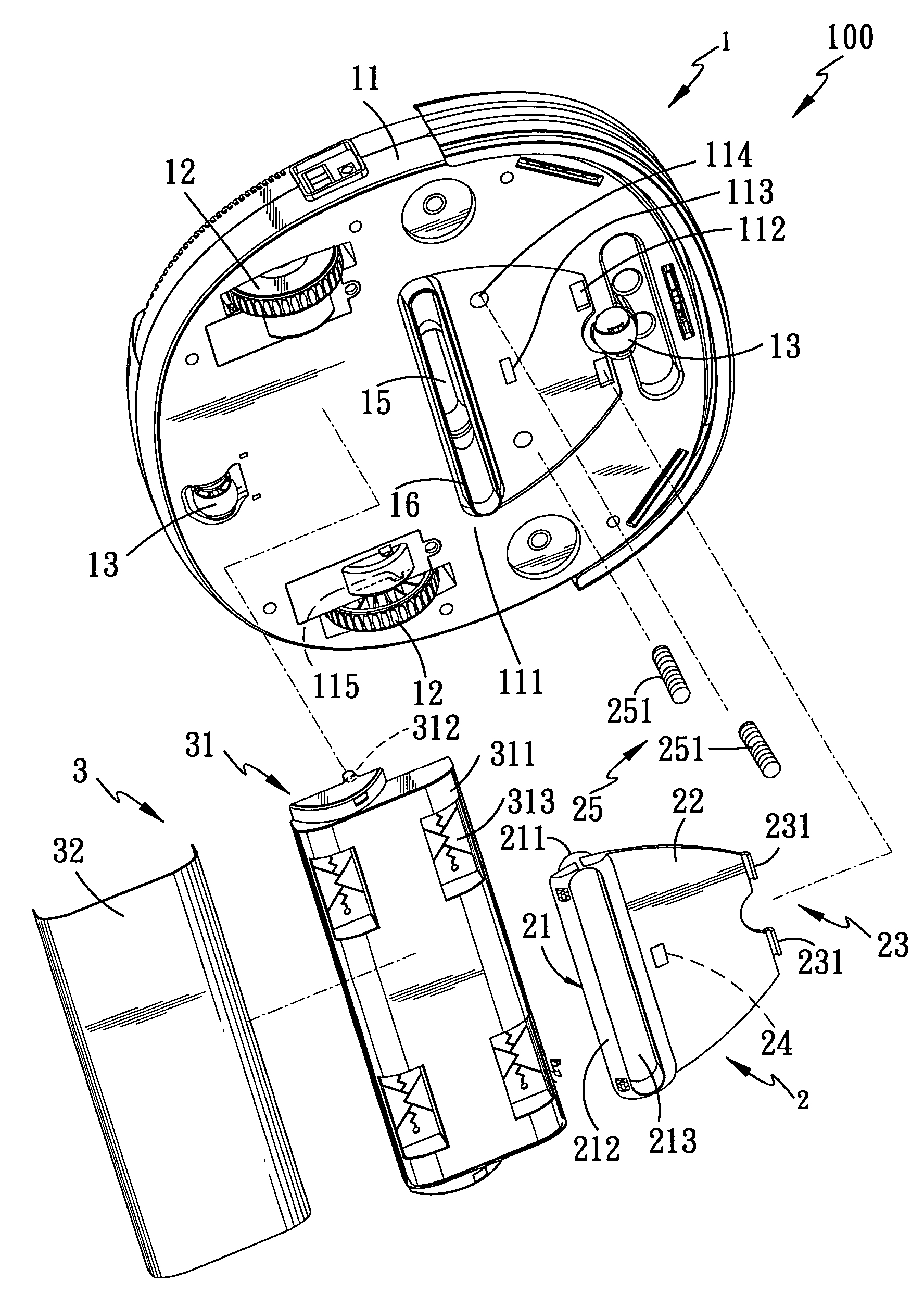
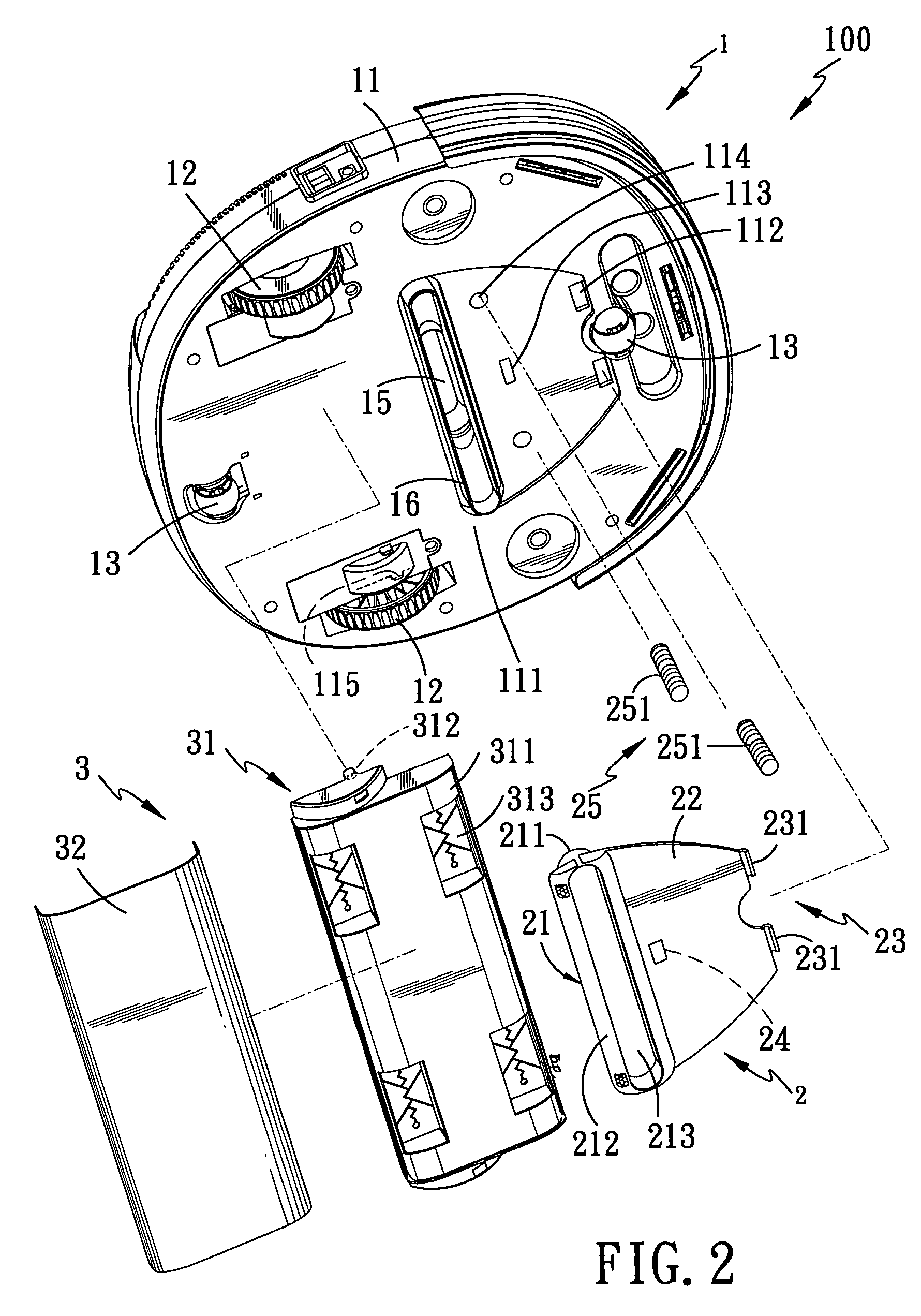
[0015]Referring to FIGS. 2 and 3, the preferred embodiment of a self-moving vacuum cleaner 100 according to the present invention is shown to comprise a cleaner body 1, an intake nozzle 2, and a wiping device 3 for cleaning a floor surface 4 (see FIG. 5).

[0016]The cleaner body 1 includes a casing 11, a pair of driving wheels 12 rotatably mounted on a bottom wall 111 of the casing 11, and two rollers 13 rotatably mounted on leading and trailing ends of the bottom wall 111, which are opposite to each other in a longitudinal direction. Control circuits and elements (not shown) are provided in the casing 11 to control a pair of motors (not shown) to actuate rotation of the driving wheels 12, respectively, thereby driving the cleaner body 1 to self-move on the floor surface 4 in a predetermined mode. Since the construction of the control circuits and elements is hitherto known, a description thereof is dispensed with herein for the sake of brevity.

[0017]With reference to FIGS. 2, 5 and 6...


PUM


Abstract

A self-moving vacuum cleaner includes a duct disposed in a casing and having a vacuum inlet which extends downwardly of a bottom wall of the casing, and an impeller disposed to draw dust from the floor surface through the vacuum inlet into the duct. An intake nozzle includes a tubular nozzle body which has an upper end communicated with and retainingly slidable relative to the vacuum inlet so as to enable a lower end of the nozzle body to be movable between upper and lower positions, and an anchoring member which is hinged to the bottom wall such that the nozzle body is swingable between the upper and lower positions in response to unevenness of the floor surface, thereby enabling the lower end to keep trailing on the floor surface when the casing moves.

Description

CROSS-REFERENCE TO RELATED APPLICATION[0001]This application claims priority of Taiwanese Application No. 092218151, filed on Oct. 9, 2003.BACKGROUND OF THE INVENTION[0002]1. Field of the Invention[0003]This invention relates to a self-moving vacuum cleaner, more particularly to a self-moving vacuum cleaner with an intake nozzle which is movable in response to an unevenness of the floor surface.[0004]2. Description of the Related Art[0005]Referring to FIG. 1, a conventional robotic vacuum cleaner is shown to include a casing 91 which has an impeller 911 and a duct 912 mounted therein. The duct 912 has a vacuum inlet 913 which extends downwardly of a bottom wall of the casing 91 for drawing dust from the floor surface 92 through the vacuum inlet 913 into the duct 912. The dust passes through a filter (not shown) and is collected in a collection bag or bin (not shown). Since the distance between the vacuum inlet 913 and the floor surface 92 is fixed, a relatively large distance may re...

Claims


Application Information

Patent Timeline
Patent Type & Authority Patents(United States)
IPC IPC(8): A47L9/02A47L5/28A47L9/06
CPCA47L5/28A47L9/02A47L9/06A47L9/0666A47L9/0686A47L2201/04
Inventor YAN, JASON
Owner HUNAN GRAND PRO ROBOT TECH
Why Eureka
Try Eureka