Apparatus and method for controlling a camera using a video compression algorithm

a technology of video compression and camera, applied in the field of system for photographing objects, can solve the problems of excessive overload of control units and unnecessary power consumption

Inactive Publication Date: 2007-07-24
SAMSUNG ELECTRONICS CO LTD
View PDF21 Cites 15 Cited by
  • Summary
  • Abstract
  • Description
  • Claims
  • Application Information

AI Technical Summary

Benefits of technology

The present invention provides a camera controlling method that uses image compression information to control the movement of the camera. This method allows for pan/tilt and zoom-in/zoom-out control based on the moving vectors that are calculated for conventional image compression, without the need for image processing to track the moving object. The technical effect of this invention is improved efficiency and accuracy in controlling the camera's movement.

Problems solved by technology

The technical problem addressed in this patent is the overload and unnecessary power consumption faced by control units in conventional automatic moving object tracking systems due to the independent processes of compressing the input image and processing it for camera control. The patent aims to develop an image compression algorithm that would enable the transmission of the moving object being tracked to a remote location using the internet or a wireless communication network.

Method used


Image

  • Apparatus and method for controlling a camera using a video compression algorithm
  • Apparatus and method for controlling a camera using a video compression algorithm
  • Apparatus and method for controlling a camera using a video compression algorithm

Examples


Embodiment Construction

[0031]The present invention will now be described in greater detail with reference to the preferred embodiment illustrated in the accompanying drawings.

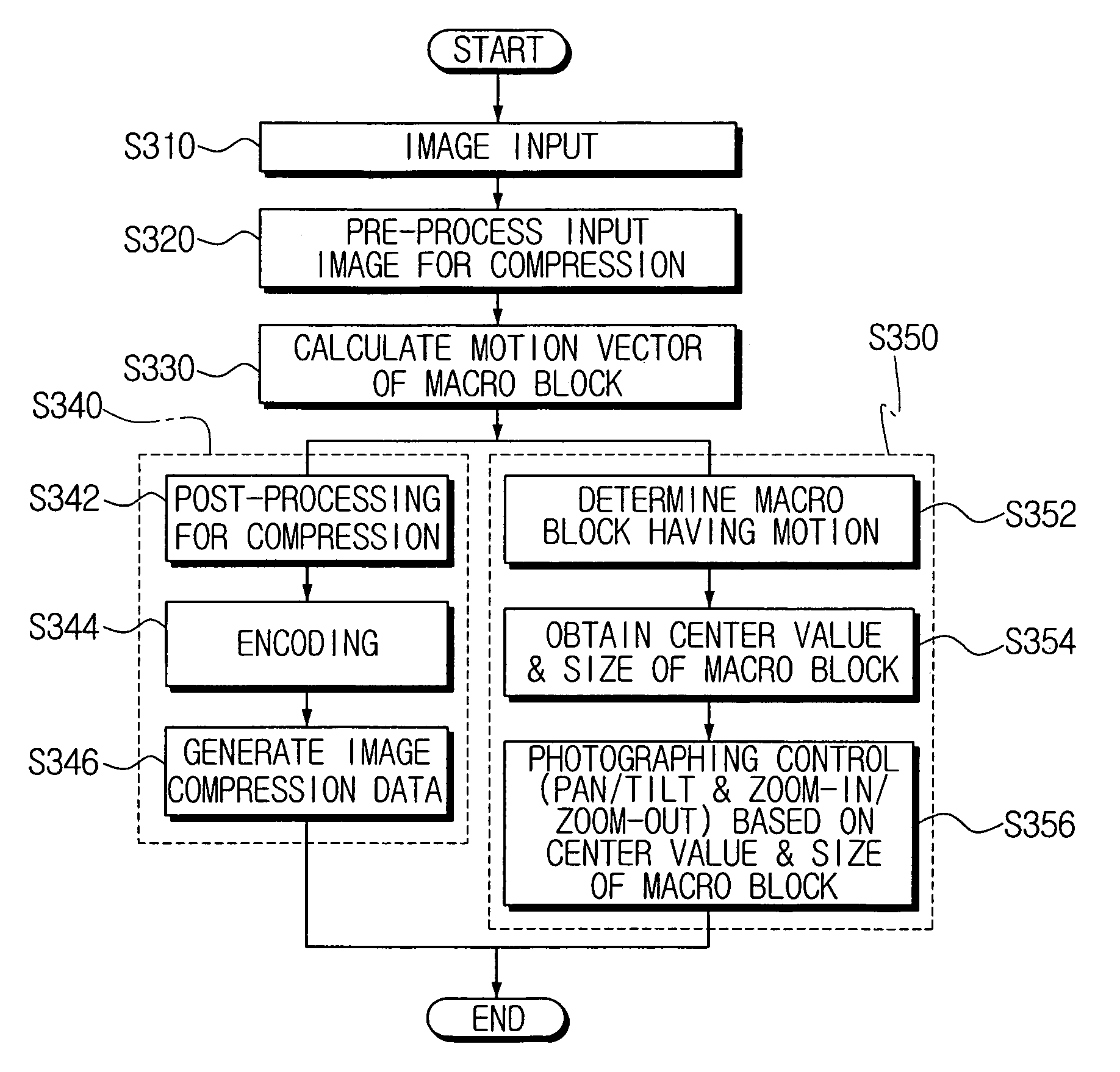
[0032]FIG. 3 is a block diagram showing a moving object tracking system according to the preferred embodiment of the present invention. The moving object tracking system includes a photographing unit 100, an image compression processing unit 200, a driving unit 300 and a photographing control unit 400.

[0033]The photographing unit 100 includes a lens (not shown) and a charge coupled device (not shown), and generates image signals while photographing a monitoring area.

[0034]The image compression processing unit 200 performs data compression in order to reduce the volume of data transmitted from the photographing unit 100, and outputs the compressed data to a storage device (not shown) or to a network transmitting device (not shown). For this purpose, the image compression processing unit 200 includes an image input unit 110 for receivi...


PUM


Abstract

A method for controlling a camera using an image compression algorithm. A motion region and a motionless region are determined with respect to an input image based on a motion vector of a macro block which is for the generation of compressed data from the input image. A center value and a size of a moving object is estimated from the motion region. According to the center value and the size of the moving object, the camera is controlled to track and photograph the moving object. Accordingly, a central processing unit of the moving object tracking system is relieved of substantial processing load, and the processing speed of the system is improved.

Description


Claims


Application Information

Patent Timeline
Owner SAMSUNG ELECTRONICS CO LTD
Why Eureka
Try Eureka