Wireless device enclosure using piezoelectric cooling structures

a piezoelectric cooling and wireless device technology, applied in the field of wireless communication, can solve the problems of increasing the heat generation (power dissipation) of wireless devices, and increasing the functional complexity of wireless chips and other processing circuitry within wireless devices

Inactive Publication Date: 2007-07-24
MICRON TECH INC
View PDF8 Cites 37 Cited by
  • Summary
  • Abstract
  • Description
  • Claims
  • Application Information

AI Technical Summary

Problems solved by technology

The functional complexity of wireless chips and other processing circuitry within wireless devices is increasing.
Such increases in functional complexity typically result in corresponding increases in heat generation (power dissipation) within the wireless devices.
As heat generation increases, a point may eventually be reached where natural convention is no longer adequate to maintain the circuitry at an acceptable operating temperature.
In addition, the power consumption of the thermal solutions themselves should be considered.
In addition, any additional thermal energy added to the inner region of a wireless device by power dissipation within the thermal solution may reduce the overall effectiveness of the thermal solution.

Method used


Image

  • Wireless device enclosure using piezoelectric cooling structures
  • Wireless device enclosure using piezoelectric cooling structures
  • Wireless device enclosure using piezoelectric cooling structures

Examples


Embodiment Construction

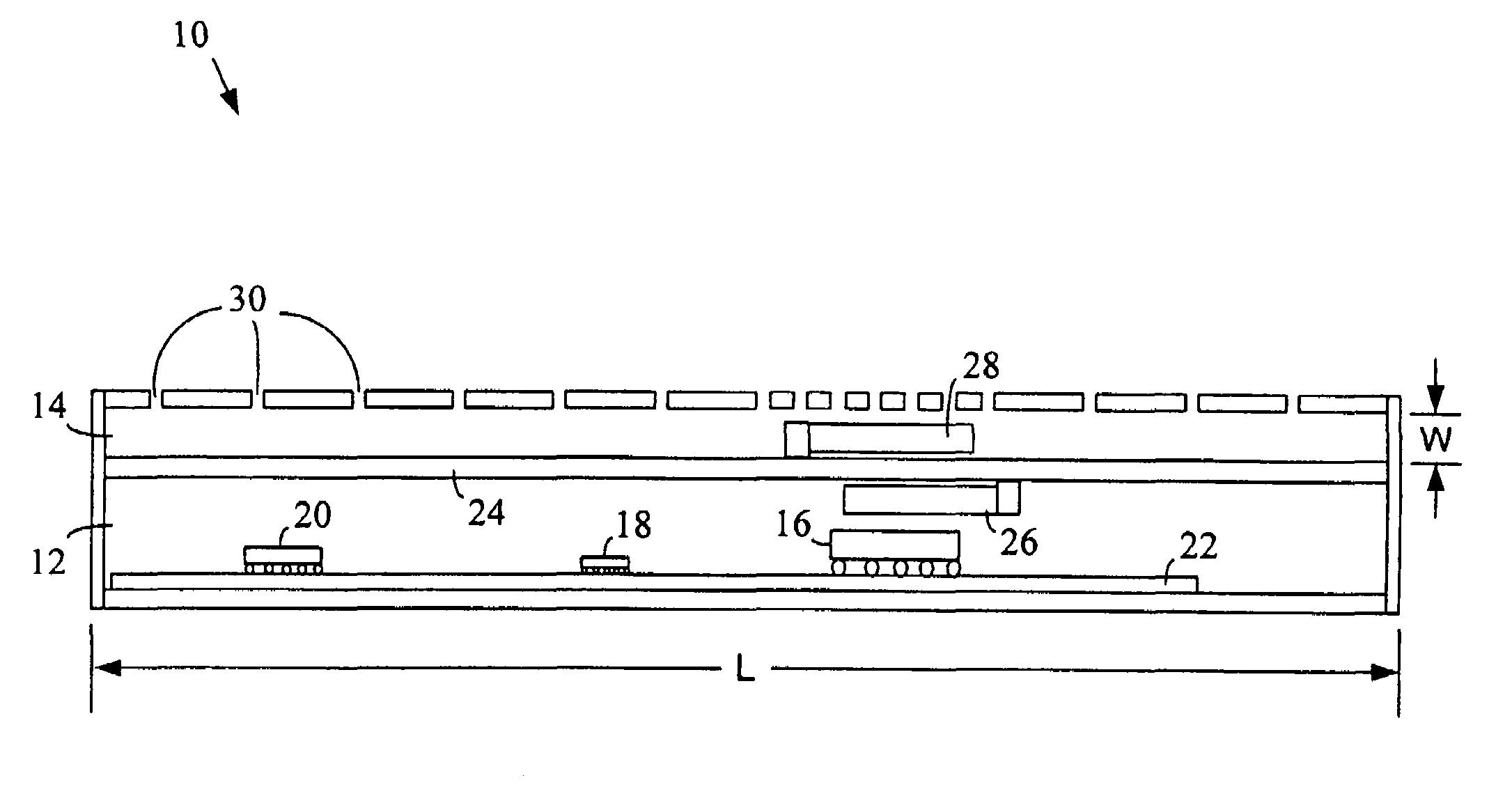
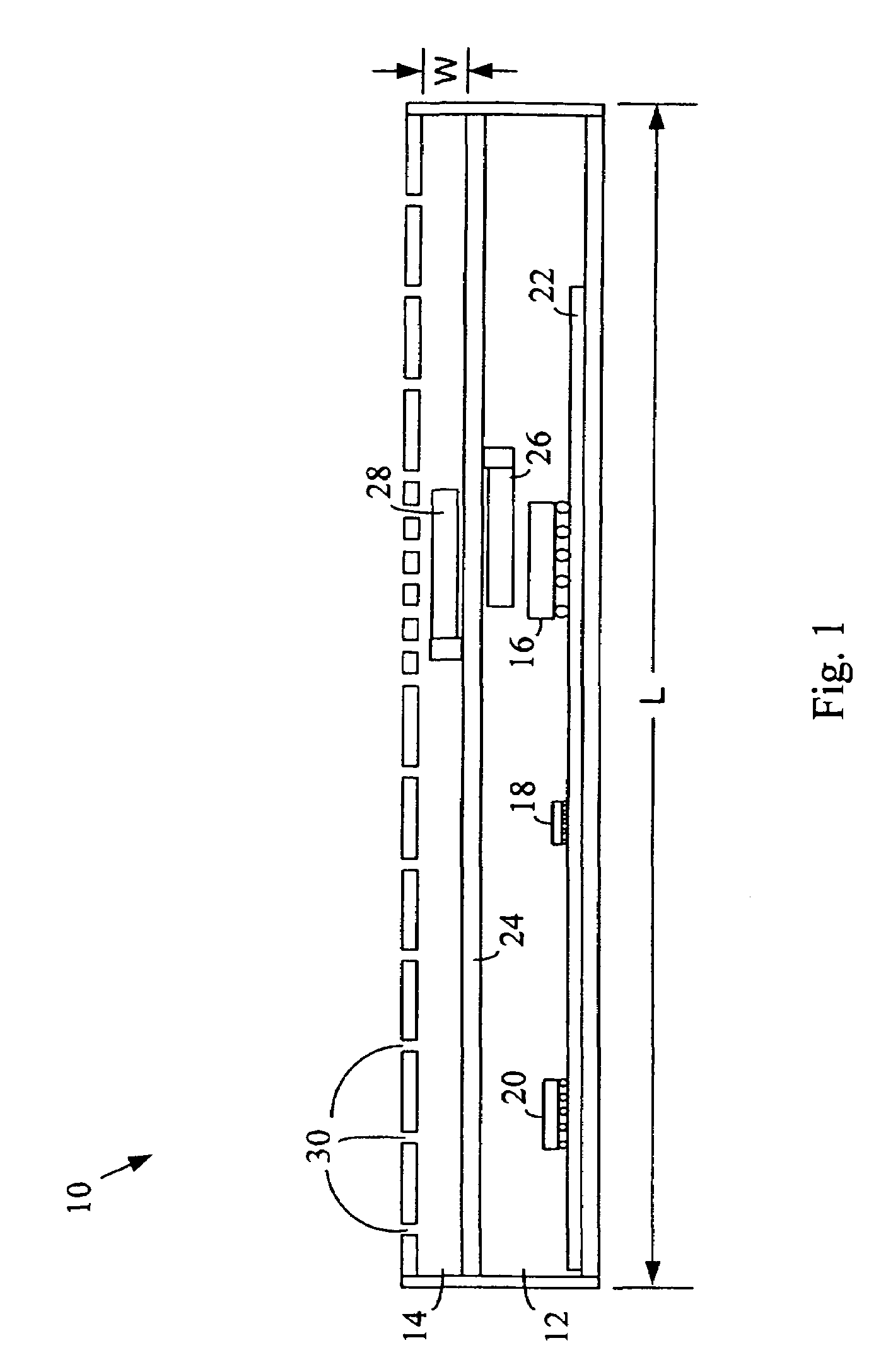
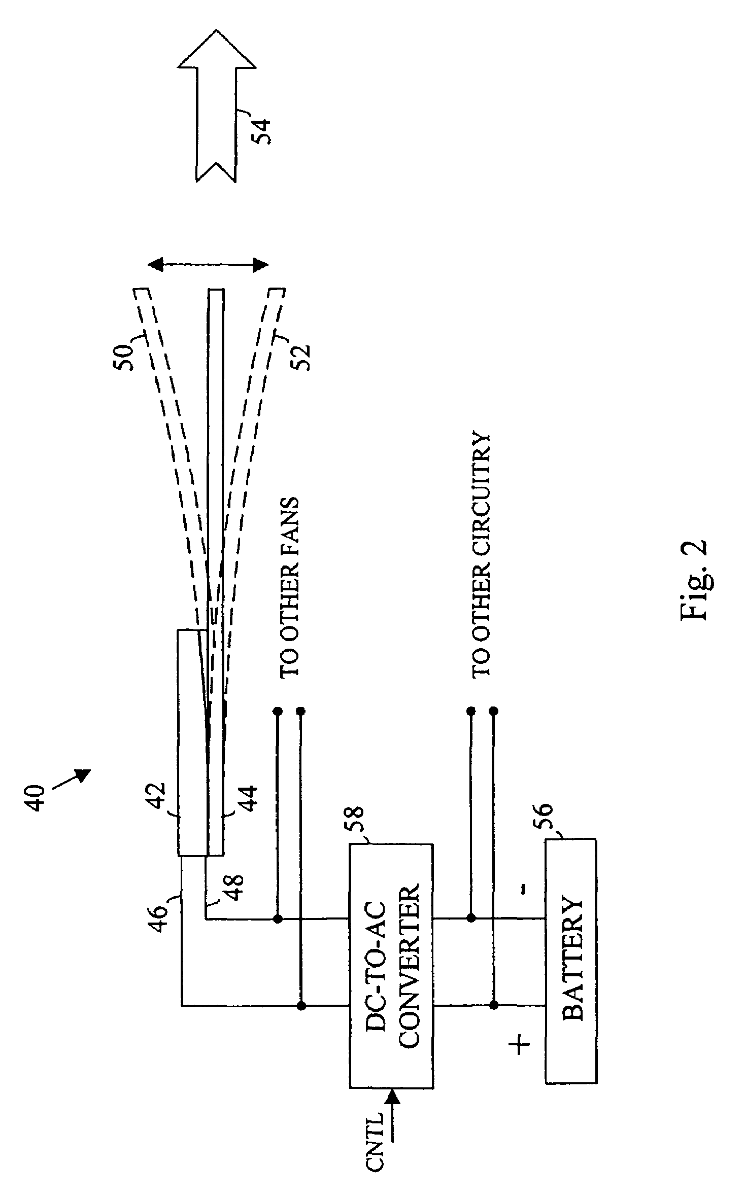
[0007]In the following detailed description, reference is made to the accompanying drawings that show, by way of illustration, specific embodiments in which the invention may be practiced. These embodiments are described in sufficient detail to enable those skilled in the art to practice the invention. It is to be understood that the various embodiments of the invention, although different, are not necessarily mutually exclusive. For example, a particular feature, structure, or characteristic described herein in connection with one embodiment may be implemented within other embodiments without departing from the spirit and scope of the invention. In addition, it is to be understood that the location or arrangement of individual elements within each disclosed embodiment may be modified without departing from the spirit and scope of the invention. The following detailed description is, therefore, not to be taken in a limiting sense, and the scope of the present invention is defined on...


PUM


Abstract

An enclosure for a wireless device includes a first compartment and a second compartment. The first compartment is to house some or all of the electronic circuitry of the wireless device and is sealed from an exterior environment. The second compartment is adjacent to the first compartment and includes one or more piezoelectric fans to provide cooling for the first compartment. The second compartment is open to the exterior environment and provides physical protection for the one or more piezoelectric fans located therein.

Description

TECHNICAL FIELD[0001]The invention relates generally to wireless communications and, more particularly, to circuit cooling techniques for use within wireless devices.BACKGROUND OF THE INVENTION[0002]The functional complexity of wireless chips and other processing circuitry within wireless devices is increasing. Such increases in functional complexity typically result in corresponding increases in heat generation (power dissipation) within the wireless devices. As heat generation increases, a point may eventually be reached where natural convention is no longer adequate to maintain the circuitry at an acceptable operating temperature. For this reason, thermal solutions may be developed to facilitate the removal of heat from the circuitry within a wireless device. As space is often limited within portable wireless devices, thermal solutions for use in such devices should be capable of implementation within relatively tight areas. In addition, the power consumption of the thermal solut...

Claims


Application Information

Patent Timeline
Patent Type & Authority Patents(United States)
IPC IPC(8): H05K7/20
CPCF04D29/582H01L23/467F04D33/00H01L2224/16225H01L2924/00011H01L2924/00014H01L2224/0401
Inventor PAYDAR, REZASAUCIUC, IOAN
Owner MICRON TECH INC
Why Eureka
Try Eureka