Path establishment method for establishing paths of different fault recovery types in a communications network

a communication network and path establishment technology, applied in the field of fault recovery methods, can solve the problems of not providing signal to the protection resource, unable to accommodate a number of communication channels of different fault recovery types in a single communications network, and significantly low probability of fault occurrence in the protection resource, so as to avoid failure to recover

Active Publication Date: 2007-07-24
NEC CORP
View PDF7 Cites 74 Cited by
  • Summary
  • Abstract
  • Description
  • Claims
  • Application Information

AI Technical Summary

Benefits of technology

[0017]It is a still further object of the present invention to provide a path establishment method that avoids unsuccessful fault-recovery which can occur as a result of fragmented time-slots.

Problems solved by technology

However, the signal is not supplied to the protection resource.
However, simultaneous occurrences of failures in both working and protection resources means that the system cannot be recovered and hence it is necessary to guarantee that probability of fault occurrences in the protection resources is significantly low.
However, the prior art route calculation and fault recovery algorithms do not allow a number of communication channels of different fault recovery types to be accommodated in a single communications network for a number of reasons.
For example, fault recovery type 1+1 allows fast recovery from failure, but it needs the same amount of backup resource for a protection path as that of its working path and does not allow the protection path to carry extra traffic.
Another problem is that the constraint route calculation algorithm is not appropriate for extra traffic since it can result in a situation where extra traffic is set up over links where 1:1 or shared type protection paths are not established.
In the fault recovery aspect of a communications network, time-slot fragmentation is still another problem.

Method used


Image

  • Path establishment method for establishing paths of different fault recovery types in a communications network
  • Path establishment method for establishing paths of different fault recovery types in a communications network
  • Path establishment method for establishing paths of different fault recovery types in a communications network

Examples


first embodiment

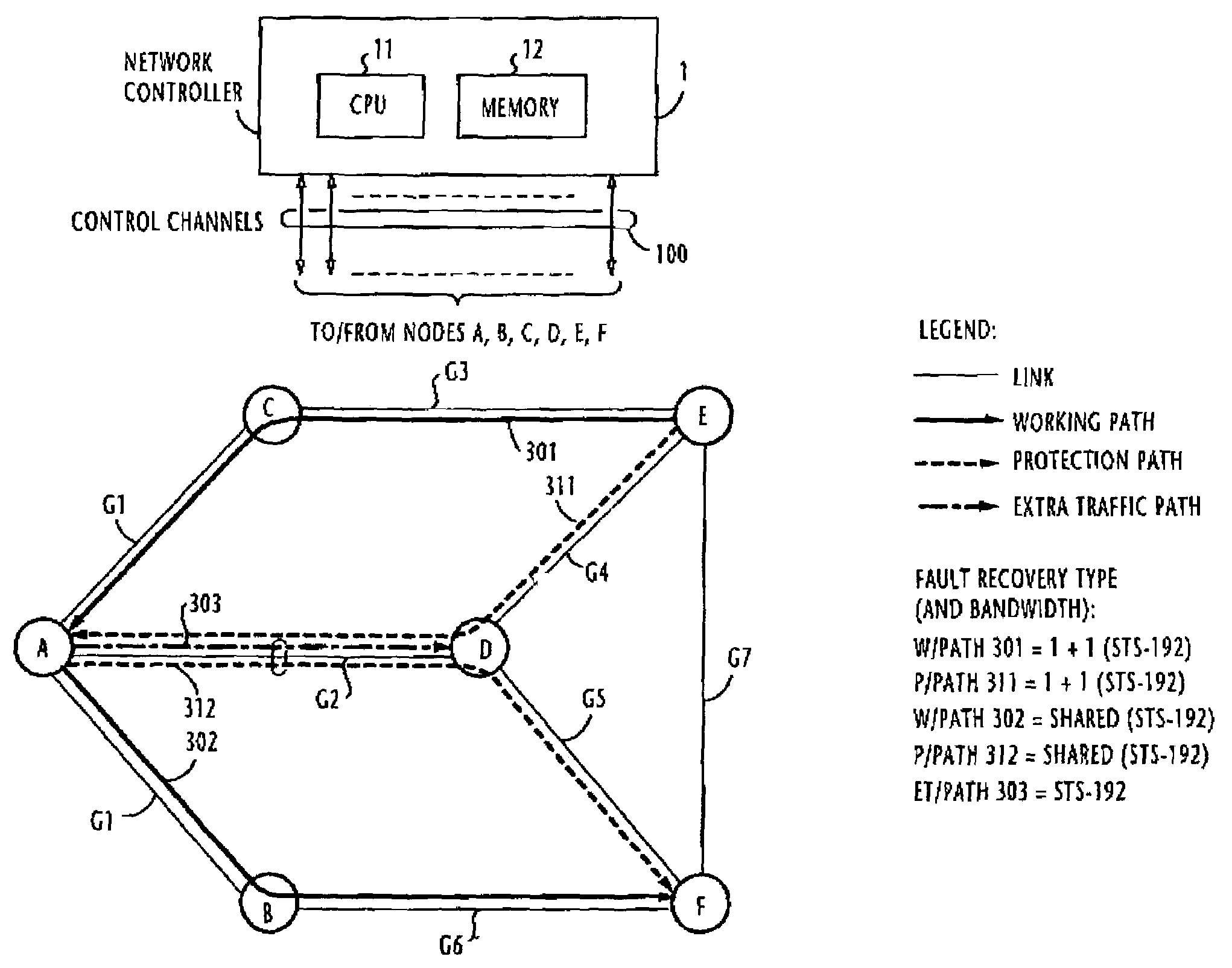
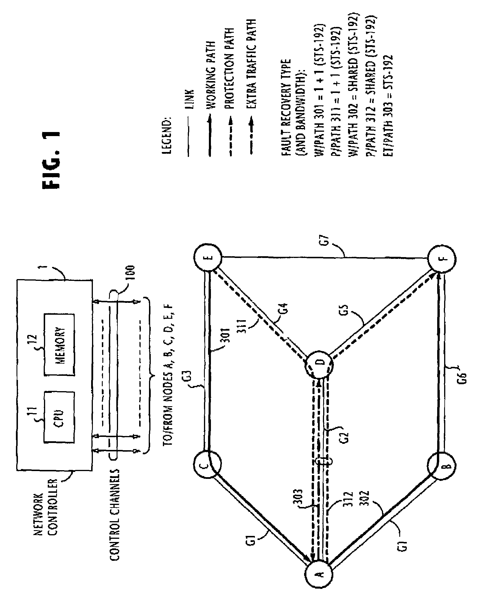
[0051]Referring now to FIG. 1, an optical communication network of this invention comprises a network controller 1 and a plurality of nodes A to F interconnected by links in a meshed configuration. For example, nodes A and B are interconnected by a link AB in the direction from node A to node B and a link BA in the direction from node B to node A. In this embodiment, it is assumed that a path is established in a single direction from an initiating node to a terminating node. All links are indicated by SRLG (shared risk link group) identifiers G1 to G7. A bundle of links that are grouped under the same G1, for example, include links AB, BA, AC and CA. All nodes are connected via control channels 100 to the network controller 1, which includes a CPU 11 and a memory 12.

[0052]One typical example of a configuration of working paths and protection paths established in the network of FIG. 1. It is assumed that a working path 301 of recovery type “1+1” is established between nodes A and E v...

second embodiment

[0145]A communications network according to the present invention is shown in FIG. 16 and the detail of node A is shown in FIG. 17. This embodiment is useful for avoiding unsuccessful fault recovery due to fragmented time-slots. In this network, instead of wavelength paths, TDM paths are established as shown in FIG. 16 which is identical in configuration to that of FIG. 1. In the illustrated example, the working and protection TDM paths 301, 311 have a bandwidth of STS-1 and the working and protection TDM paths 302, 312 have a bandwidth of STS-3. The extra traffic path 303 has a bandwidth of STS-1 which occupies a portion of the STS-3 bandwidth the shared-type protection path 312.

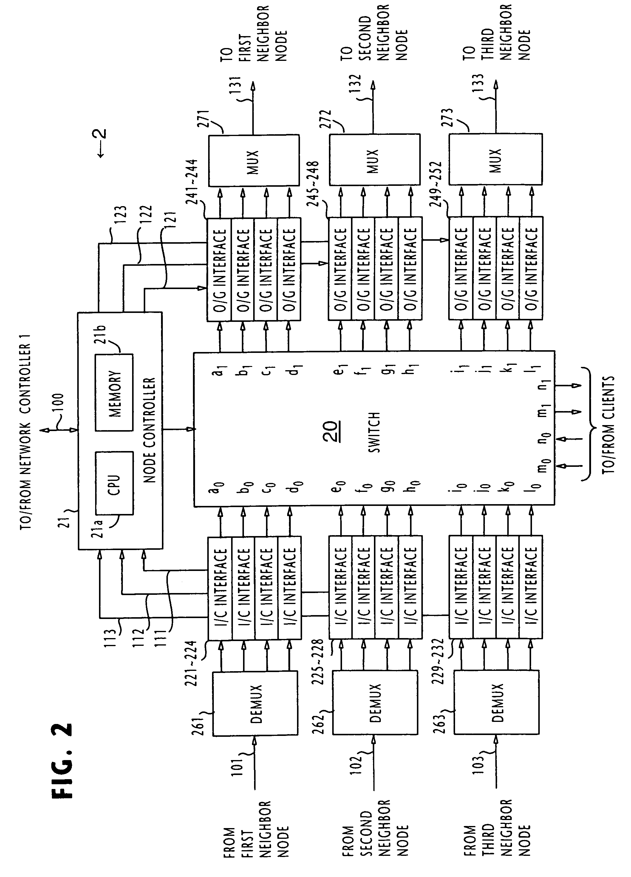
[0146]In FIG. 17, the switch 20 of node A has input ports a0, b0, c0 for receiving TDM signals from neighbor nodes and output ports a1, b1, c1 for transmitting TDM signals to neighbor nodes. Input and output ports m0 and m1 are connected to a client terminal.

[0147]In FIG. 18A, a port table of the node A is ...


PUM


Abstract

In a communications network where multiple shared risk link groups are formed by links having a common risk, unreserved bandwidths are defined corresponding to all SRLG's and a maximum bandwidth of each link is set as an initial value of each of the defined unreserved bandwidths when a working path or a protection path of “1+1” or “1:1” recovery type is requested. When a protection path of “shared” recovery type is requested, unreserved bandwidths are defined corresponding to the SRLG's to which the links of its corresponding working path belong and a maximum bandwidth of each link is set as an initial value to each of the defined unreserved bandwidths. The bandwidth of the working or protection path is subtracted from each of the unreserved bandwidths. The request is rejected if a minimum of the subtracted values is smaller than a threshold.

Description

BACKGROUND OF THE INVENTION[0001]1. Field of the Invention[0002]The present invention relates generally to fault recovery methods, and more particularly to a path establishment method for a meshed network that can be recovered from failure using different fault recovery types.[0003]2. Description of the Related Art[0004]In a public communication network, fault recovery is an indispensable task. Meshed network configuration has met with wide acceptance because of its versatile fault recovery features. A fault recovery method using GMPLS (Generalized Multi-Protocol Label Switching) technology in a mesh network is described in an Internet Draft “Generalized Multi-Protocol Label Switching (GMPLS) Architecture”, draft-ietf-ccamp-gmpls-architecture-01.txt which Eric Mannie submitted in IETF (Internet Engineering Task Force) (hereinafter Document 1). According to Document 1, chapter 12, a fault recovery method is classed in protection and restoration modes. In the protection mode, a failur...

Claims


Application Information

Patent Timeline
Patent Type & Authority Patents(United States)
IPC IPC(8): H04L1/00H04J14/02H04L1/22H04L45/24H04L45/243H04L45/247H04Q11/00
CPCH04J14/0227H04J14/0294H04J14/0295H04L1/22H04J14/0228H04J14/0284H04Q2011/0081H04Q2011/0086H04Q2011/0088
Inventor ISHIBASHI, OSAMUSUEMURA, YOSHIHIKO
Owner NEC CORP
Why Eureka
Try Eureka