Low-profile, multi-axis, highly passively damped, vibration isolation mount

a vibration isolation and multi-axis technology, applied in the direction of shock absorbers, machine supports, cosmonautic vehicles, etc., can solve the problems of not affording the desired level of laterally directed vibration isolation, affecting and limiting the damage within the device. , to achieve the effect of modest increase in the longitudinal profile of the overall payload and the vehicle, and modest increase in the effective plan profile of the payload

Active Publication Date: 2007-07-31
MOOG INC
View PDF7 Cites 40 Cited by
  • Summary
  • Abstract
  • Description
  • Claims
  • Application Information

AI Technical Summary

Benefits of technology

[0014]The advantage achieved by the present invention relative to the prior art is the introduction of a vibration isolation device affording particularly prescribed longitudinal and lateral compliances with significantly high passive damping, and having commensurate advantage of a very modest increase of longitudinal profile of the overall payload and vehicle. Further, through the shaping of the flexure element plan view contours, the increase in the payload's effective plan profile can be kept quite modest and allow spacecraft-to-fairing clearances to not be appreciably increased, if at all.
[0015]As with the referenced invention of U.S. Pat. No

Problems solved by technology

Damping within that device was also limited to the constrained-layer-on-beam-bending damping approach of the time, and effective primarily for longitudinal motions.
Other earlier approaches for vibration isolation and damping implementation wherein elastomers are used in the primary load path, remain inferior to those which maintain use of high-strength, linearly elastic materials throughout the primar

Method used


Image

  • Low-profile, multi-axis, highly passively damped, vibration isolation mount
  • Low-profile, multi-axis, highly passively damped, vibration isolation mount
  • Low-profile, multi-axis, highly passively damped, vibration isolation mount

Examples


Embodiment Construction

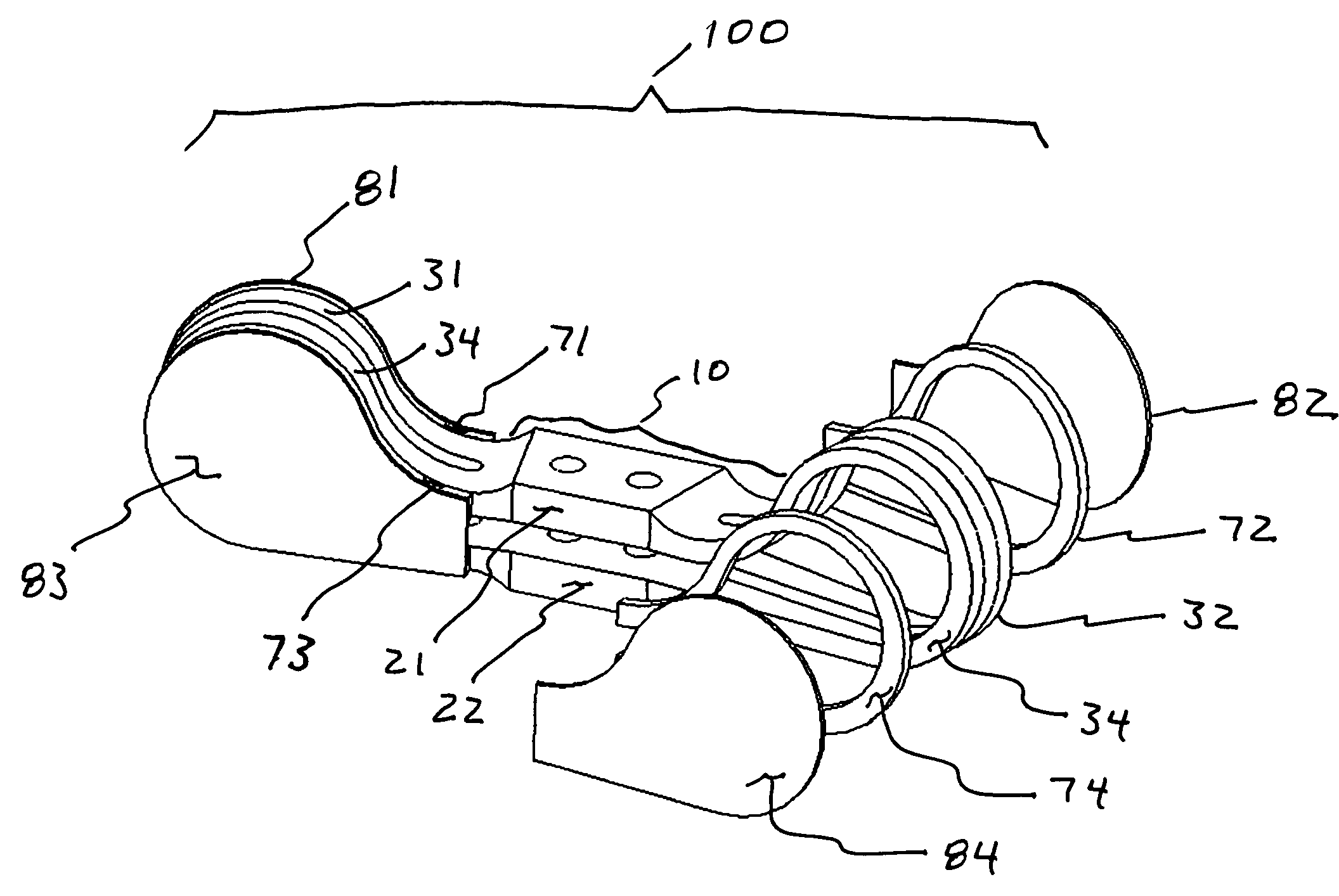
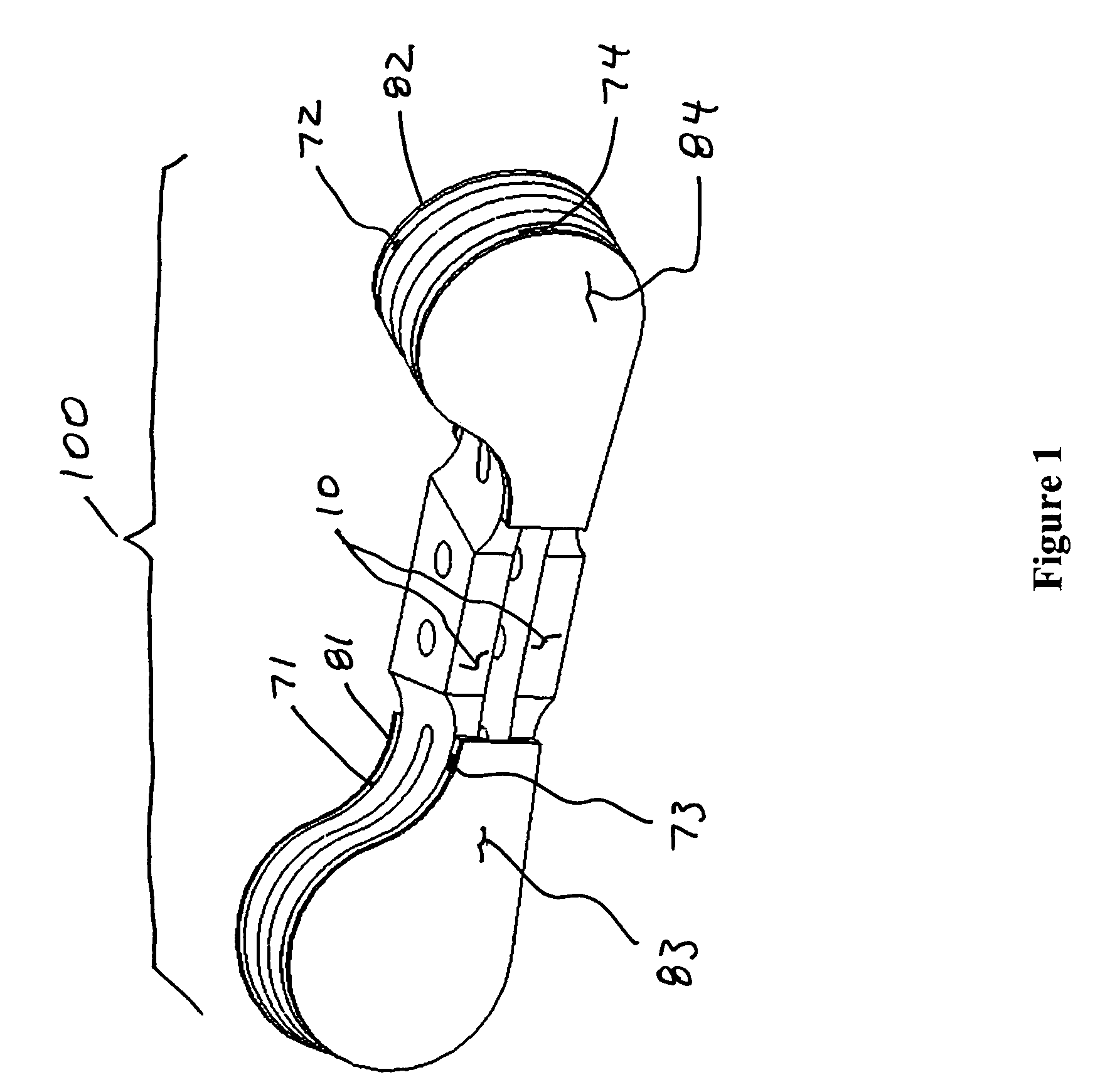
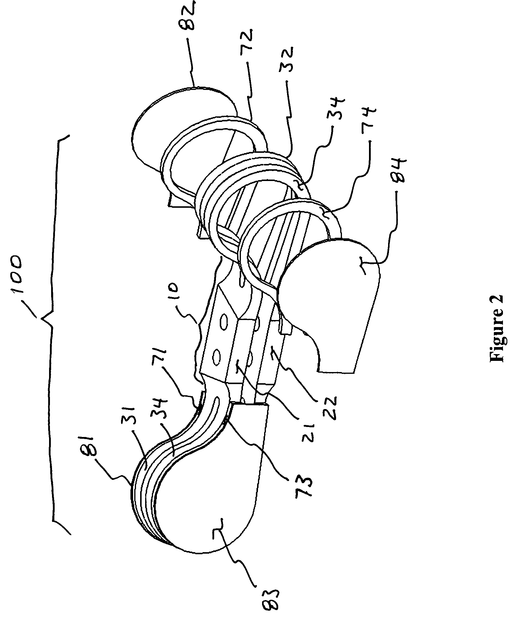
[0022]A preferred embodiment of the invention is shown in FIG. 1 and a partially exploded view of this embodiment is shown in FIG. 2. As shown in FIG. 1 the assembled vibration isolation mount 100 is comprised of a flexure element 10, VEM layers 71 through 74, and stiff constraining layers 81 through 84. For the presently described embodiment within flexure element 10, flexure loop sections 31 through 34 are also comprised and denoted.

[0023]FIG. 2 shows the relationship of the VEM and stiff constraining layers relative to the flexure element 10. In the exploded portion of the view, VEM layer 72 is seen on one of its faces to attach to flexure loop section 32. In the present embodiment VEM layer 72 is cut and shaped to match the shape of the flexure loop section 32. Constraining layer 82 attaches to the opposite face of the VEM layer 72 and spans across the flexure loop section 32 so that motion of the upper flexure section relative to the lower flexure section causes shearing of the...


PUM

PropertyMeasurementUnit
Strengthaaaaaaaaaa
Distanceaaaaaaaaaa
Stiffnessaaaaaaaaaa

Abstract

The invention disclosed is a low-profile, multi-axis, highly passively damped, vibration isolation mount which when used in multiplicity provides a complete vibration load isolation mounting system. The device provides in unique fashion a very low profile interface in combination with independently determinable compliance in all directions of vibration loading. Substantial passive damping is afforded without sacrifice to strength and linearity of behavior through adaptation of a shear wall type constrained layer damping. The result is a highly passively damped vibration isolation device that provides a very low profile interface, wide ranging longitudinal and lateral compliance management, in a durable, reliable, lightweight, and compact form.

Description

BACKGROUND OF THE INVENTION[0001]The present invention relates to passively damped, vibration and shock load isolation apparatus suitable for use in protecting hardware and payloads from damaging vibration and shock loads, particularly those extreme loads seen in spacecraft launch systems. This application incorporates by reference all that disclosed within U.S. Pat. No. 6,202,961.[0002]The ability to isolate payloads from the vibration and shock loading of a supporting structure or vehicle, or conversely to isolate a structure or vehicle from the vibrations of an engine, motor, or other vibration inducing payload is of great value to the aerospace, automobile and vehicle industries world wide. The particular ability to provide substantial passive damping and vibration isolation in a compact and lightweight form, together with a completely linear elastic, high-strength load path has been the strength of the device disclosed in U.S. Pat. No. 6,202,961.[0003]A further characteristic o...

Claims


Application Information

Patent Timeline
IPC IPC(8): F16F3/08
CPCF16F3/08F16F7/10
Inventor WILKE, PAUL S.JOHNSON, CONOR D.
Owner MOOG INC
Why Eureka
Try Eureka