[0015]Accordingly, it is a principle advantage of the present invention to overcome some or all of these limitations and to provide an improved design for the arrangement of vents within a building.
[0016]In one aspect, the present invention provides a building comprising a substantially air-impervious bottom floor, a generally vertical exterior wall structure, one or more generally vertical interior walls within the exterior wall structure, and a roof. The exterior wall structure surrounds at least a portion of the bottom floor and defines an outer periphery of the building. The exterior wall structure is substantially air-impervious except for the presence of a plurality of wall-vents therein, the wall-vents permitting airflow through the exterior wall structure. The one or more interior walls define a plurality of rooms of the building, each of the one or more interior walls acting as a division between two of the rooms. The one or more interior walls are substantially air-impervious except for the presence of one or more wall-vents in the one or more interior walls. Each of the one or more wall-vents permits airflow through one of the one or more interior walls. The roof is positioned above the bottom floor, the exterior wall structure, and the one or more interior walls. The roof is substantially air-impervious except for the presence of one or more roof-vents therein. Each of the one or more roof-vents is oriented generally along a planar portion of the roof and permits airflow between an airspace immediately underneath the roof and within the building and an airspace immediately above the roof.
[0017]In another aspect, the present invention provides a building comprising a bottom floor, a generally vertical exterior wall structure, a roof, and a ceiling. The bottom floor is substantially air-impervious except for the presence of one or more floor-vents therein. Each of the one or more floor-vents permits airflow between an airspace immediately above the bottom floor and an airspace immediately below the bottom floor. The exterior wall structure surrounds at least a portion of the bottom floor and defines an outer periphery of the building. The exterior wall structure is substantially air-impervious except for the presence of a plurality of wall-vents therein, the wall-vents permitting airflow through the exterior wall structure. The roof is positioned above the bottom floor and the exterior wall structure and is substantially air-impervious except for the presence of one or more roof-vents therein. Each of the one or more roof-vents is oriented generally along a planar portion of the roof and permits airflow between an airspace immediately underneath the roof and within the building and an airspace immediately above the roof. The ceiling is positioned below the roof so that the ceiling and the roof define an attic space therebetween. The ceiling is substantially air-impervious except for the presence of one or more ceiling-vents therein. Each of the one or more ceiling-vents is oriented generally along a planar portion of the ceiling and permits airflow between the attic airspace and an airspace immediately below the ceiling.
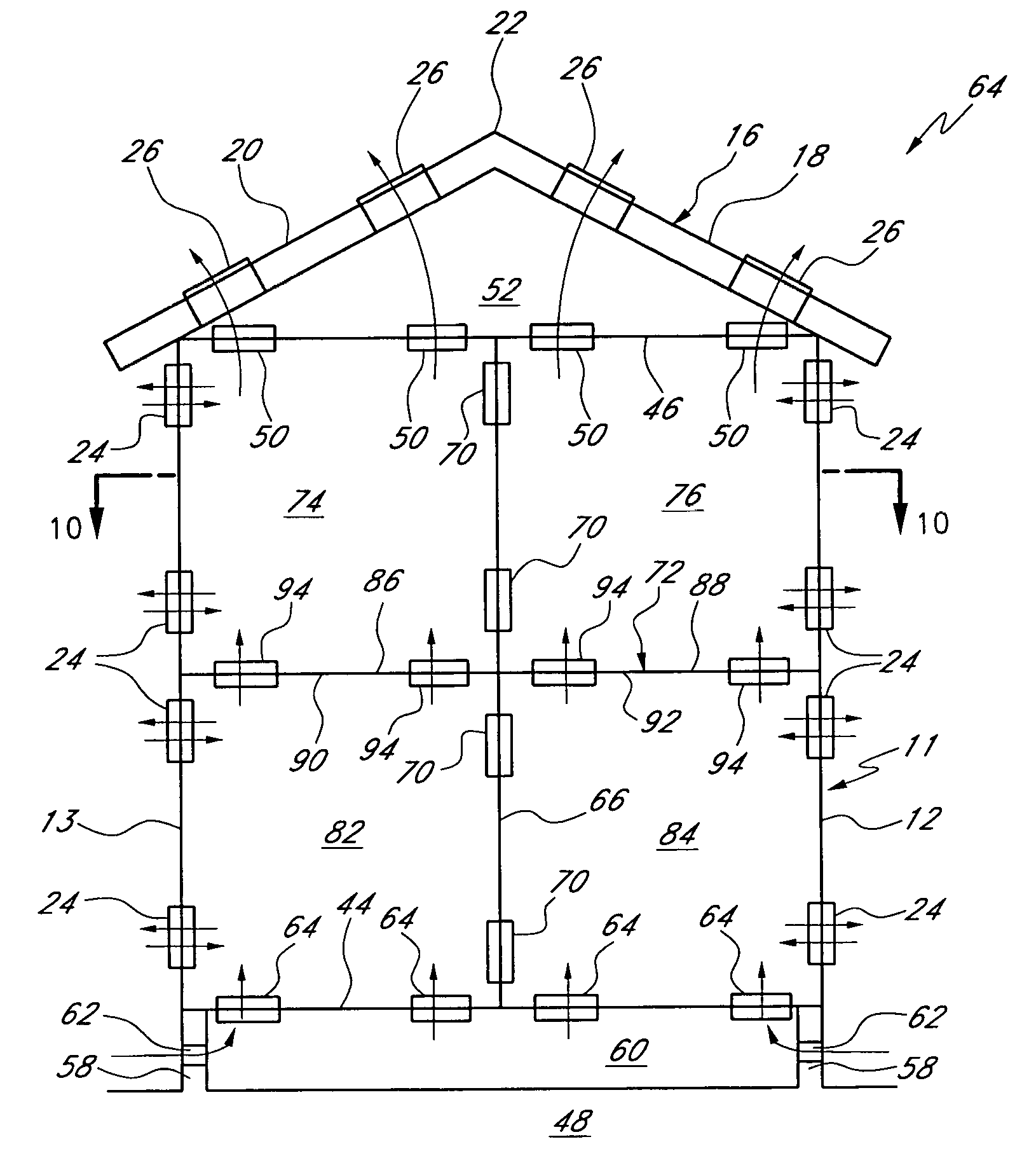
[0018]In another aspect, the present invention provides a multiple story building comprising a substantially air-impervious bottom floor, a generally vertical exterior wall structure, one or more generally vertical interior walls within the exterior wall structure, one or more generally horizontal structures elevated above the bottom floor and dividing the building into multiple stories, and a roof. The exterior wall structure surrounds at least a portion of the bottom floor and defines an outer periphery of the building. The exterior wall structure is substantially air-impervious except for the presence of a plurality of wall-vents therein, the wall-vents permitting airflow through the exterior wall structure. The one or more generally vertical interior walls define a plurality of rooms of the building. Each of the one or more interior walls acts as a division between two of the rooms. The one or more interior walls are substantially air-impervious except for the presence of one or more wall-vents therein. Each of the one or more wall-vents permits airflow through one of the one or more interior walls. Each of the one or more horizontal structures defines a floor of at least one room immediately above the horizontal structure and a ceiling of at least one room immediately below the horizontal structure. Each of the one or more horizontal structures is substantially air-impervious except for the presence of at least one ceiling-floor vent therein. The at least one ceiling-floor vent of each horizontal structure is oriented generally along a planar portion of the horizontal structure and permits generally vertical airflow through the horizontal structure. The roof is positioned above the bottom floor, the exterior wall structure, the one or more interior walls, and the one or more horizontal structures.
[0019]In yet another aspect, the present invention provides a building comprising a generally vertical exterior wall structure defining an outer periphery of the building, and a room within the exterior wall structure. The exterior wall structure is substantially air-impervious except for the presence of a plurality of wall-vents in the exterior wall structure, the wall-vents permitting airflow through the exterior wall structure. The room is defined by a plurality of dividing structures that are substantially air-impervious. Each of the dividing structures has a plurality of corner sections. Dividing-structure vents are provided in at least half of the corner sections of one of the dividing structures. Each of the dividing-structure vents permits airflow through its dividing structure.
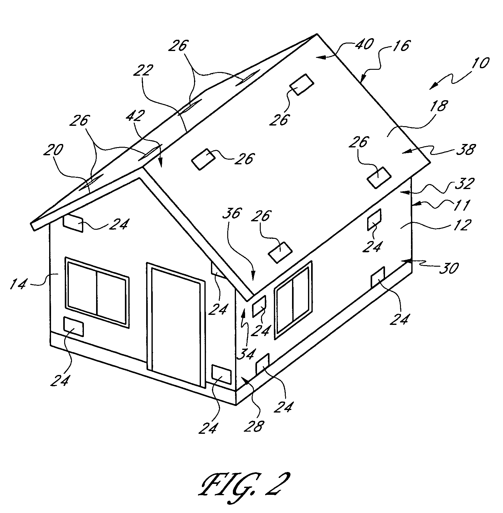
[0020]In yet another aspect, the present invention provides a building comprising a bottom floor, a generally vertical exterior wall structure surrounding at least a portion of the bottom floor and defining an outer periphery of the building, and a roof positioned above the bottom floor and the exterior wall structure. The exterior wall structure is substantially air-impervious except for the presence of a plurality of wall-vents therein, the wall-vents permitting airflow through the exterior wall structure. The roof comprises one or more generally flat roof-portions joined together. Each of the roof-portions has a plurality of corner sections and is substantially air-impervious except for the presence of roof-vents that are oriented generally along a planar portion of that roof-portion and are positioned in at least half of the corner sections of that roof-portion. Each of the roof-vents permits airflow generally vertically through the roof.

