Cable trough

a cable trough and cable technology, applied in the direction of cable junctions, electric cable installations, building components, etc., can solve the problems of affecting the travel of trains over railway lines, and affecting the protection of cables

Inactive Publication Date: 2007-07-31
PREMIER CUSTOM TROUGH
View PDF11 Cites 11 Cited by
  • Summary
  • Abstract
  • Description
  • Claims
  • Application Information

AI Technical Summary

Problems solved by technology

However, because of the nature of the materials from which railway lines are constructed, it is inadvisable to simply bury a cable beneath a railroad line.
The pressures and abrasive action of the ballast used to support railway lines quickly degrade any cables buried without protection.
In addition, repairs to cabling may interfere with the travel of trains over the railway lines.
Concrete, both pre-cast and cast-in-place, is extremely heavy and therefore installation may be quite expensive.
Extruded plastic cable troughs, both unreinforced and reinforced with randomly oriented fiber strands, have relatively low strengths and, accordingly, shorter life spans and reduced ability to withstand the rigors of installation adjacent a railway lines.
Cast or molded thermoplastic materials having randomly oriented fibers tend to be somewhat stronger than unreinforced types of cabling trough, but are quite expensive.
Steel cable trough can also be quite expensive.

Method used


Image

  • Cable trough
  • Cable trough
  • Cable trough

Examples


Embodiment Construction

[0015]Although the disclosure hereof is detailed and exact to enable those skilled in the art to practice various embodiments, the physical embodiments herein disclosed merely exemplify the invention which may be embodied in other specific structures. While certain embodiments have been described, the details may be changed without departing from the invention, which is defined by the claims.

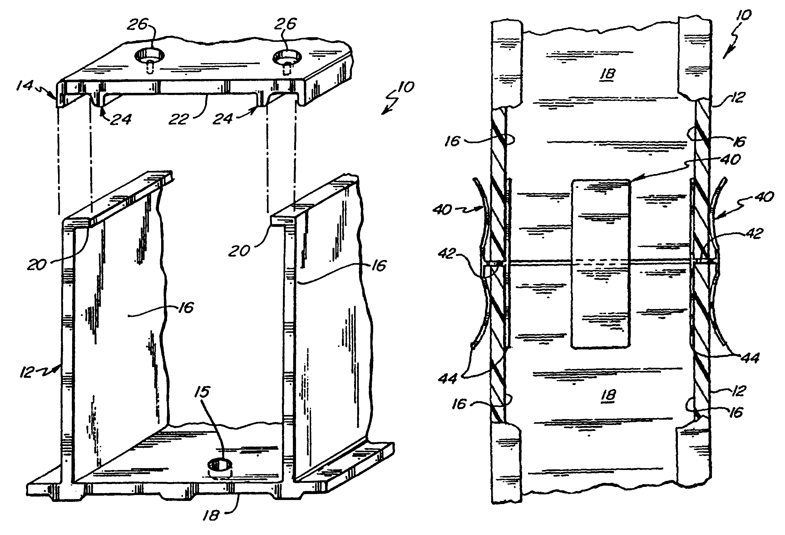
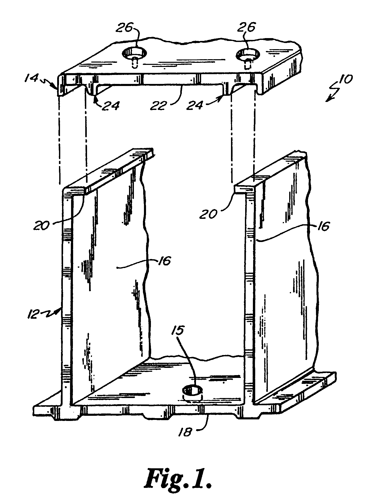
[0016]Cable trough is typically installed alongside railway lines, either above grade or below grade, depending on the application. Above-grade installations of cable trough may be made directly on the surface of the ballast that supports a railway line, or in an elevated position where the cable trough has been secured to, for example, the wall of a railway tunnel.

[0017]FIG. 1 illustrates a cross-section of a typical cable trough constructed and arranged according to one example embodiment. Note that any dimensions appearing in the figures are by way of illustration only and it is to be underst...


PUM


Abstract

A cable trough for installing cables alongside a railway line or other right of way is described. The cable trough is constructed using longitudinally oriented reinforcing fibers coated with polymeric resin that generally aligns the reinforcing fibers with the length of the cable trough. One or more connector clips may be used to secure respective portions of the cable trough to one another. The cable trough is provided with a cover that may be removably secured to an elongate channel to protect the cables housed within the cable trough. Elbows, corners, tees, and other connectors may be provided to run the cable trough in any desired direction. A method of installing cables in a cable trough is also described.

Description

CROSS REFERENCE TO RELATED APPLICATIONS[0001]This application is a continuation-in-part of U.S. patent application Ser. No. 10 / 495,500, filed May 13, 2004, which issued as U.S. Pat. No. 7,034,227 on Apr. 25, 2006, and which claims the benefit of Provisional Application Ser. No. 60 / 404,688 filed Aug. 19, 2002, and priority to International PCT Application Serial No. PCT / US03 / 25867, filed Aug. 19, 2003.TECHNICAL BACKGROUND[0002]The disclosure relates to a conduit system adapted for containing and protecting various types of wiring laid alongside, beneath, or otherwise adjacent to railroad tracks.BACKGROUND[0003]Railroad lines provide an ideal location for the placement of various types of cabling. Included in this group are electrical cables and other types of communication cabling. However, because of the nature of the materials from which railway lines are constructed, it is inadvisable to simply bury a cable beneath a railroad line. The pressures and abrasive action of the ballast ...

Claims


Application Information

Patent Timeline
Patent Type & Authority Patents(United States)
IPC IPC(8): H02G3/04H02G3/06H02G9/04
CPCH02G3/0418H02G3/0437H02G3/0608H02G9/04
Inventor FOX, RONALD W.
Owner PREMIER CUSTOM TROUGH
Why Eureka
Try Eureka