Stick lever unit for radio controlled device and radio controlled device equipped with the same

a technology of radio controlled devices and lever units, which is applied in the direction of mechanical control devices, pulse techniques, coding, etc., can solve the problems of long time and troublesome work, and achieve the effect of easy replacement of resilient plates

Inactive Publication Date: 2007-07-31
FUTABA CORPORATION
View PDF7 Cites 18 Cited by
  • Summary
  • Abstract
  • Description
  • Claims
  • Application Information

AI Technical Summary

Benefits of technology

[0018]An object of the present invention is to provide a stick lever unit, in which a user can easily change a resilient plate in the stick lever unit, without replacement of the resilient plate.
[0019]Another object of the present invention is to provide a radio-controlled device having a stick lever unit, in which a user can easily change the resilient plate in the stick lever unit, without opening the housing of the radio-controlled device.
[0026]In the stick lever unit for a radio-controlled device according to the present invention, two types of resilient plates, each in different shape, are provided as a pressure member configuring a stick lever holding mechanism. By adjusting the distance of a resilient plate spaced from the fixing member with the adjustment member, a user can suitably select a desired resilient plate. For that reason, there is the advantage in that a user can easily change the resilient plate in the stick lever unit, without replacing the resilient plate.
[0027]The adjustment screw can be directly adjusted from the outside of the radio-controlled device equipped with the stick lever unit, by means of a screwdriver or wrench. Therefore, there is the advantage in that adjustment can be easily performed without opening the housing of the radio-controlled device.

Problems solved by technology

This work has been troublesome.
Further, when a resilient plate to be replaced is not at hand or the user himself cannot replace the resilient plate, the product has to be sent to the manufacturer to ask for the replacement of the resilient plate.
This is troublesome and takes much time which is very inconvenient.

Method used


Image

  • Stick lever unit for radio controlled device and radio controlled device equipped with the same
  • Stick lever unit for radio controlled device and radio controlled device equipped with the same
  • Stick lever unit for radio controlled device and radio controlled device equipped with the same

Examples


Embodiment Construction

[0040]The best mode for embodying the present invention will be described below by referring to the Figures.

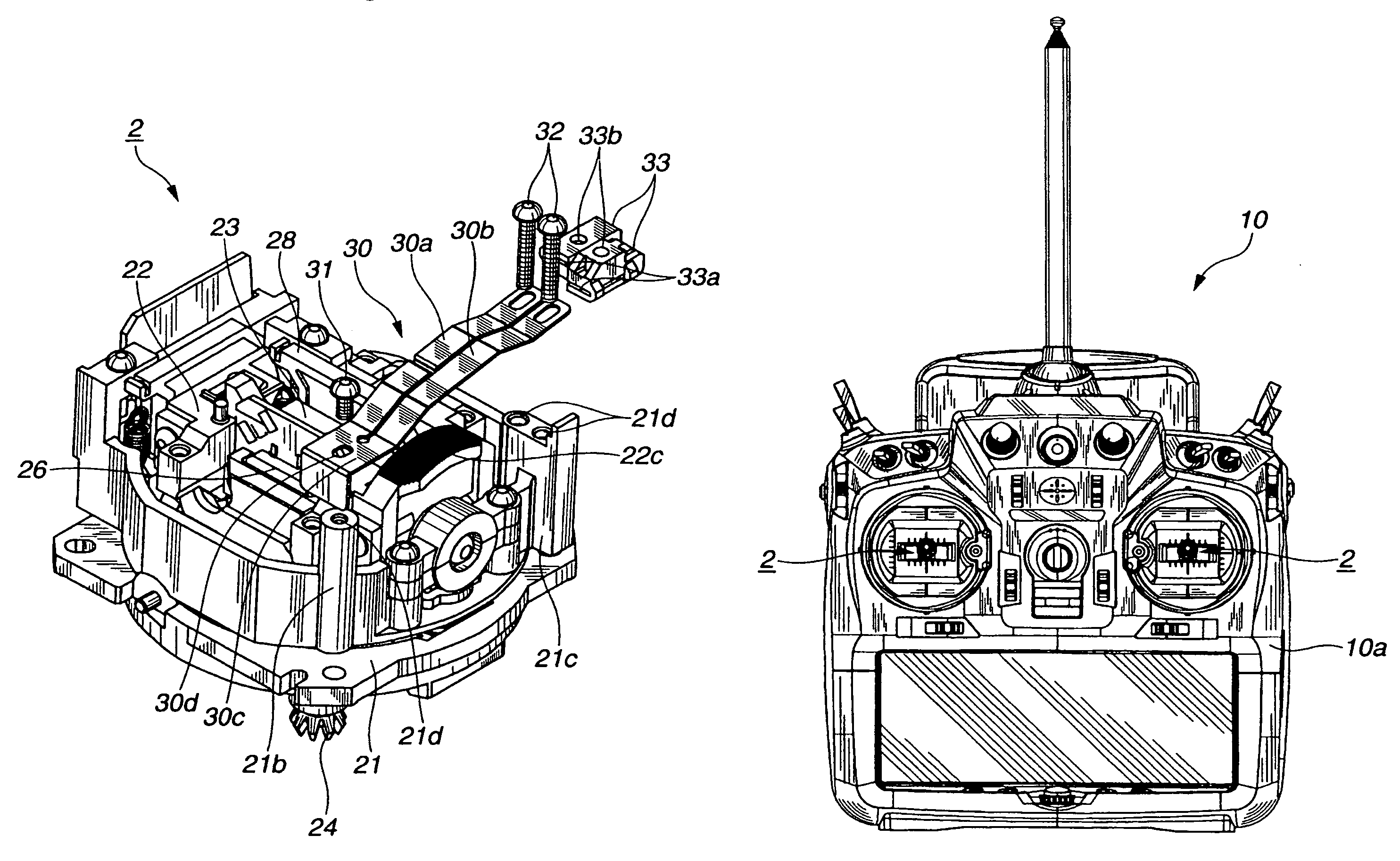
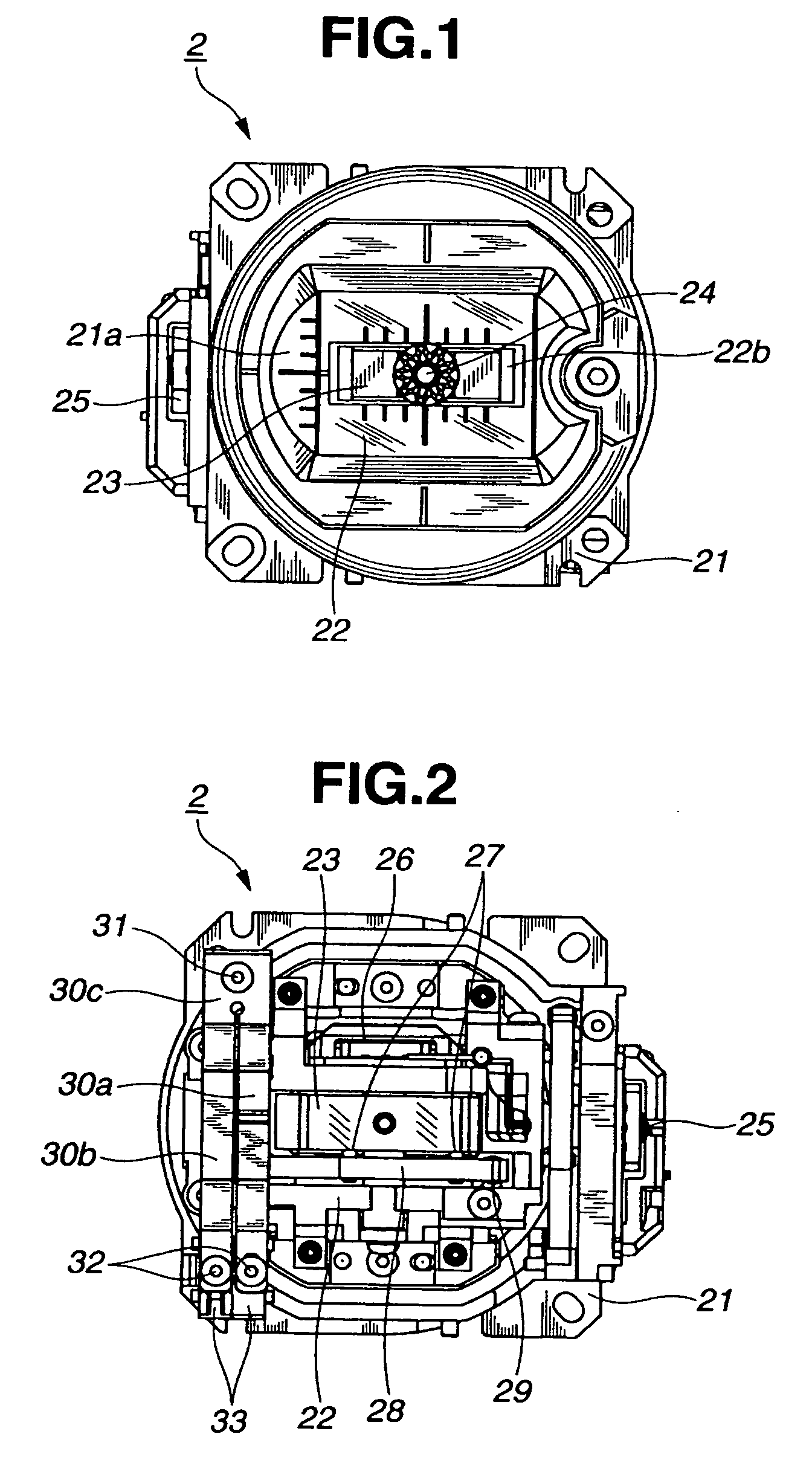
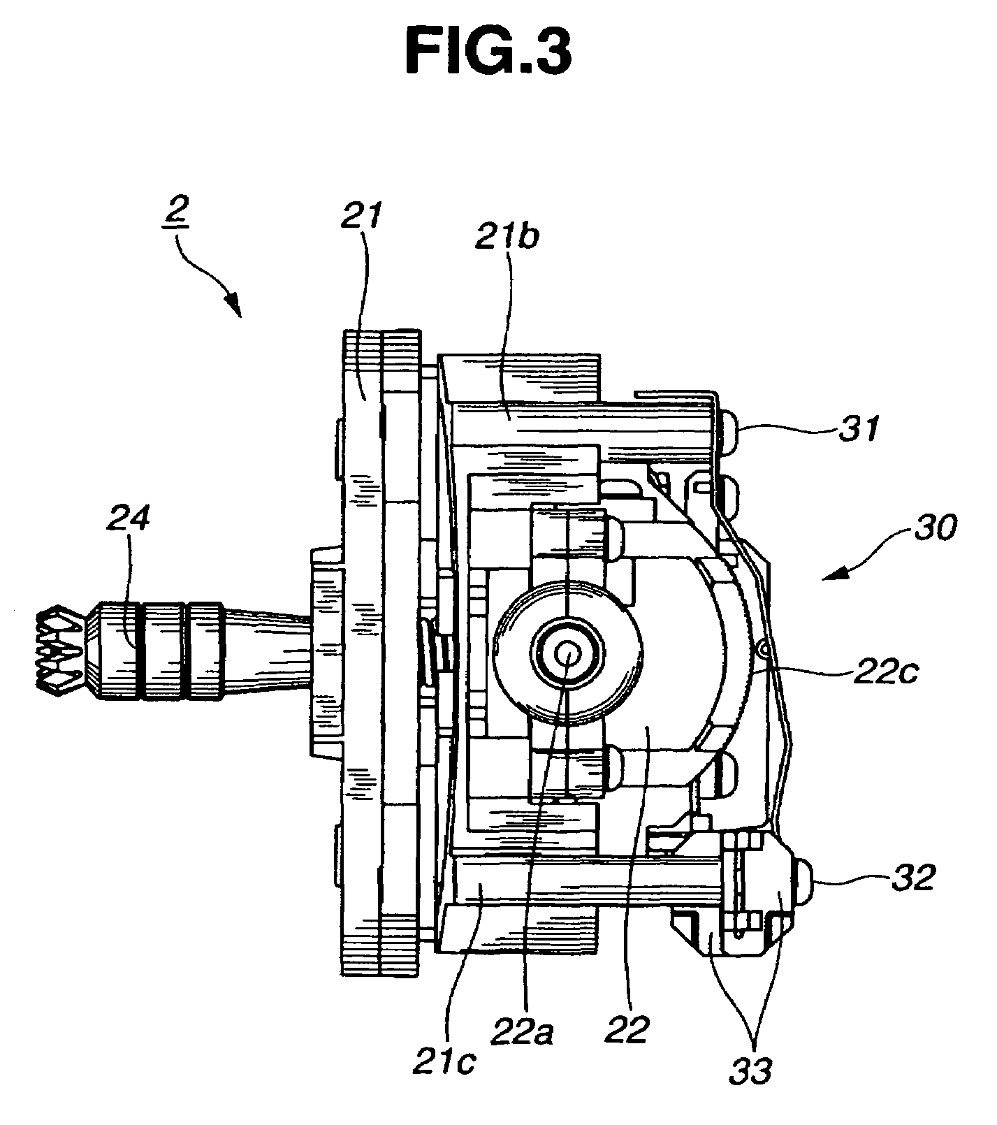
[0041]A stick lever unit for a radio-controlled device (hereinafter, a stick lever unit), according to the present invention has substantially the basic configuration similar to that shown in FIGS. 10 and 11 described in the background art. However, specific shapes of respective constituent elements are different from those of that shown in FIGS. 10 and 11. Accordingly, the portions related to the stick lever holding mechanism, being a main portion of the present invention, will be explained below. Like reference numerals are used to designate to the portions corresponding to those in FIGS. 10 and 11 so that the duplicate explanation is omitted.

[0042]As shown in FIGS. 1 to 4, the rotational frame (rotational member) 22 of the stick lever unit 2 according to the present invention has an arc-shaped groove 22c forming a mechanism for holding the stick lever 24. The arc-shaped gro...


PUM


Abstract

A stick lever unit for a radio-controlled device that is capable of easily changing the type of stick lever holding mechanism by a user is provided. The stick lever unit includes a fixing member to which a variable resistor is attached, a rotational member equipped with a stick lever, the rotational member being journaled to the fixing member and having an arc-shaped groove on a periphery thereof, and a pressure member bridged to the fixing member for pressing the arc-shaped groove. The pressure member has resilient plates of two types which can be suitably selected by means of an adjustment member.

Description

CROSS REFERENCES TO RELATED APPLICATIONS[0001]This application claims the priority benefit of Japanese Patent Application No. 2004-290798 filed on Oct. 1, 2004.STATEMENT REGARDING FEDERALLY SPONSORED RESEARCH[0002]Not Applicable.BACKGROUND OF THE INVENTION[0003]The present invention relates to stick lever units for radio-controlled devices, which remotely maneuver controllable bodies, such as model airplanes, model helicopters, and cars, or boats, by controlling a stick lever. More particularly, the present invention relates to radio-controlled devices, having the stick lever unit.[0004]A stick lever unit for radio control (hereinafter, referred to as a stick lever unit) is equipped on radio-controlled devices (radio-control devices for models), each of which remotely controls manipulated bodies, such as model airplanes, model helicopters, model cars, and model boats (refer to Japanese Utility Model Publication No. 62-87697).[0005]The stick lever unit is shown in FIG. 9. In the conv...

Claims


Application Information

Patent Timeline
Patent Type & Authority Patents(United States)
IPC IPC(8): H01C10/30
CPCA63H30/04H01C10/34G05G2009/04748H01H25/06
Inventor ARAI, MASAHIROTOKITA, MASASHIISONO, TAKAHIRO
Owner FUTABA CORPORATION
Why Eureka
Try Eureka