Multi-axial bone anchor system

Inactive Publication Date: 2007-08-07
SDGI HLDG
View PDF55 Cites 73 Cited by
  • Summary
  • Abstract
  • Description
  • Claims
  • Application Information

AI Technical Summary

Benefits of technology

[0009]The present invention provides, in one embodiment, an orthopedic implant system including a plate member for placement adjacent and along one or more bones, such as vertebrae, and having a longitudinal axis. The plate member includes at least one slot substantially parallel to the plate axis, which slot includes a channel portion that extends through substantially the entire longitudinal dimension of the plate member. Also provided is a stabilizer including an opening therethrough substantially bounded by a wall, the opening having a longitudinal axis and the stabilizer further including at least one finger portion extending laterally with respect to the opening axis, wherein said finger portion is received within the

Problems solved by technology

Such features enable bone anchors to be placed at angles which are optimal for anchoring, thus reducing the chance of loosening, pull-out or other movement of the anchors while not compromising the optimal positioning of the fixation plate.
The compression fit of the bolt and collar within the plate can present difficulty in a

Method used


Image

  • Multi-axial bone anchor system
  • Multi-axial bone anchor system
  • Multi-axial bone anchor system

Examples


Embodiment Construction

[0034]For the purposes of promoting an understanding of the principles of the invention, reference will now be made to the embodiment illustrated in the drawings and specific language will be used to describe the same. It will nevertheless be understood that no limitation of the scope of the invention is thereby intended, such alterations and further modifications in the illustrated device, and such further applications of the principles of the invention as illustrated therein, being contemplated as would normally occur to one skilled in the art to which the invention relates are also included.

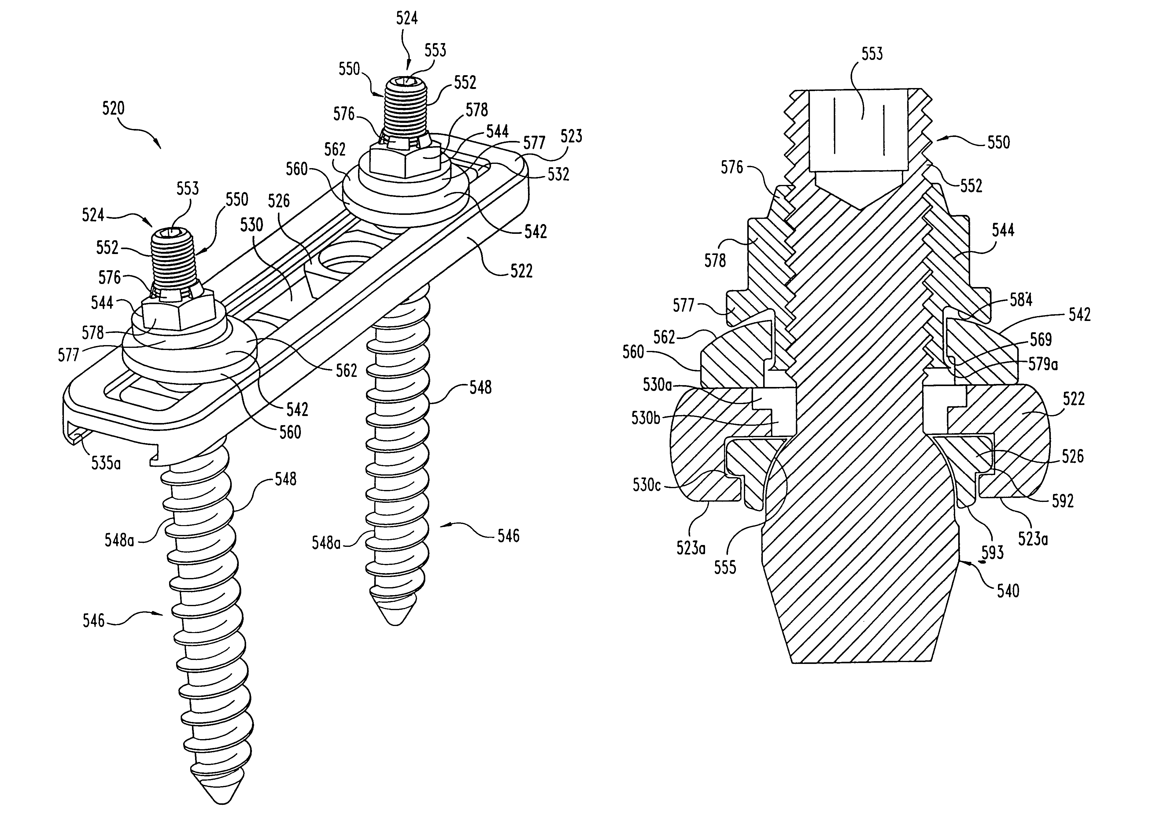
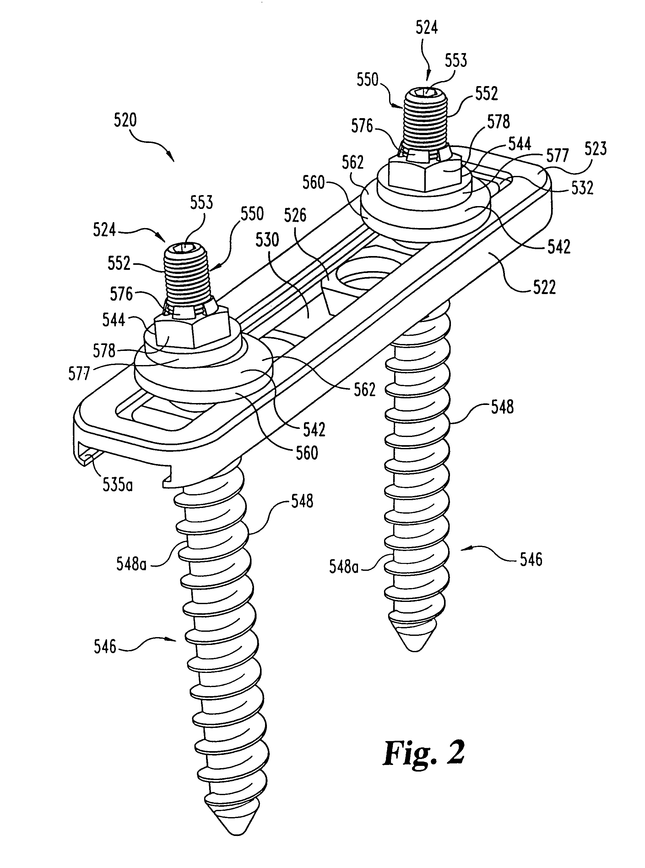
[0035]Referring generally to FIGS. 2-3, one embodiment of the orthopedic implant system 520 of the present invention is illustrated. In that embodiment, implant system 520 includes an elongated member such as a bone plate 522, a pair of bone anchor assemblies 524 and a set of supports or stabilizers 526. Differing numbers of any of these elements may be utilized without departing from the scop...


PUM


Abstract

A multi-axial bone fixation implant includes an elongated member, one or more bone anchor assemblies, and stabilizer members fitted within the elongated member. A bolt having a bone-threaded end and a machine-threaded end and an enlarged medial portion is also provided. The bolt is anchored into a bone, and its machine-threaded end passes through the elongated member and the stabilizer, and is engaged by a coupled washer and nut. The washer includes an oblong aperture, and the nut includes a projecting sleeve. The sleeve is inserted into the washer and expanded, and the washer retains the sleeve without impairing relative rotatability or translatability of the nut and washer. When locked by the nut and washer, the enlarged portion of the bolt is forced against the stabilizer, which locks against the elongated member. The elongated member can be fixed with respect to the anchor at an infinite number of multi-axial angles.

Description

[0001]This application is a continuation of U.S. patent application Ser. No. 09 / 978,932, filed Oct. 16, 2001, now issued U.S. Pat. No. 6,689,133, which is a continuation of application Ser. No. 09 / 526,188, filed Mar. 15, 2000, now issued as U.S. Pat. No. 6,315,779; which claims benefit of provisional application No. 60 / 149,774, filed Aug. 19, 1999, and provisional application No. 60 / 129,587 filed Apr. 16, 1999.FIELD OF THE INVENTION[0002]The present invention relates to an orthopedic implant assembly for use in stabilizing bone members in a desired spatial relationship and correcting bone mis-alignment disorders. In particular, the invention concerns a multi-axial spinal fixation system incorporating an elongated member such as a plate.BACKGROUND OF THE INVENTION[0003]In the art of orthopedic surgery, and particularly in spinal surgery, it has long been known to affix an elongated member, such as a plate or rod, to bones in order to hold them and support them in a given position. Fo...

Claims


Application Information

Patent Timeline
IPC IPC(8): A61B17/56A61B17/58A61B17/70A61B19/00
CPCA61B17/7007A61B17/701A61B17/8047A61B2019/307Y10S606/907A61B2090/037
Inventor MORRISON, MATTHEW M.BARKER, B. THOMASYOUNG, JOHN STEWARTBEALE, JEFFREY W.JOHNSON, CHRIS E.
Owner SDGI HLDG
Why Eureka
Try Eureka