AI technical title is built by Patsnap AI team. It summarizes the technical point description of the patent document.
a shock absorber and amplitude-dependent technology, applied in the direction of shock absorbers, mechanical equipment, transportation and packaging, etc., can solve the problems of at least heard jolts and impermissible steep acceleration of piston rods, and achieve reliable cementing or vulcanization, fewer local strains, and a soft performance curve
Active Publication Date: 2007-08-14
THYSSENKRUPP BILSTEIN +1
View PDF15 Cites 26 Cited by
Summary
Abstract
Description
Claims
Application Information
AI Technical Summary
This helps you quickly interpret patents by identifying the three key elements:
Problems solved by technology
Method used
Benefits of technology
Benefits of technology
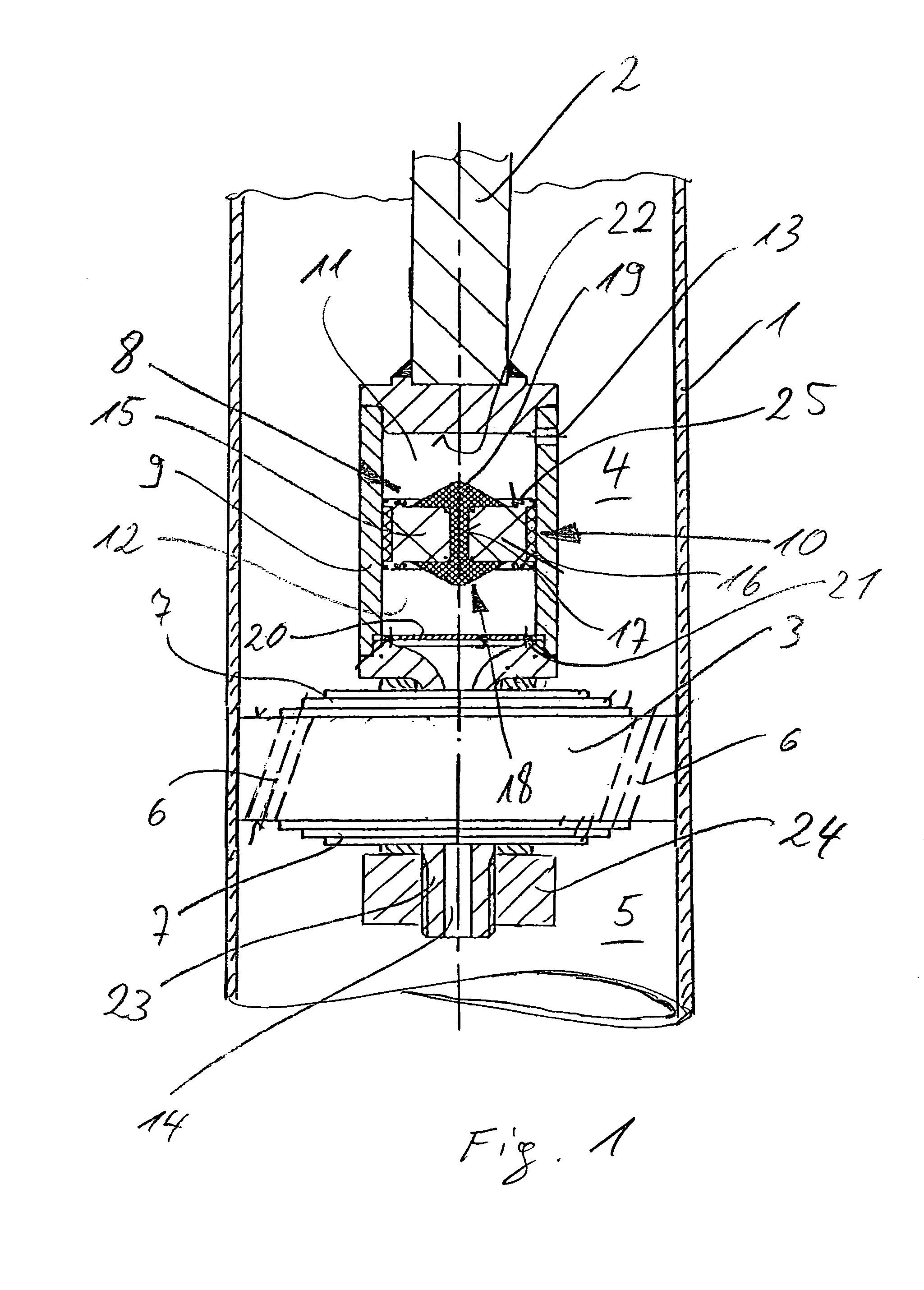
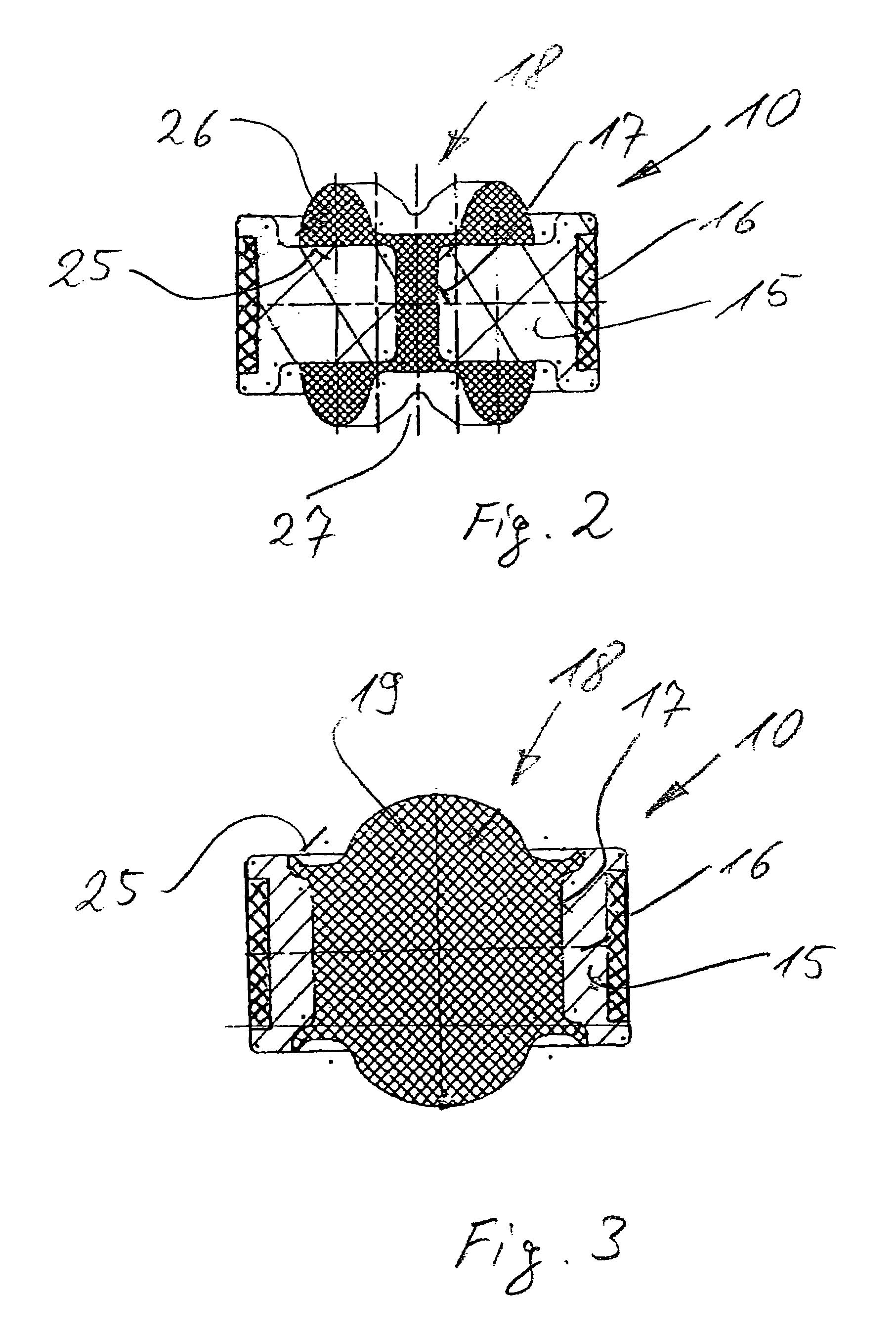
[0004]According to the present invention, the elastomeric bumper is accordingly accommodated in a hollow that extends axially through the body of the floating piston. This approach has several advantages. Any deformation will be distributed more uniformly over a wider area of the bumper, and hence there will be fewer local strains in the material. The performance curve can be softer. Another advantage is more reliable cementing or vulcanization to the floating piston's body. There will be less noise and less wear, considerably extending the component's life. In special applications, when the hollow through the body of the floating piston is very wide, the bumper can even be in one piece, with heads on each side that extend over each face. The bumper will accordingly be locked into position in the body of the floating piston in addition to any other means of fastening it.
[0005]One embodiment of the present invention features an alternative approach to shock absorption at one end of the floating piston. Here, the floating piston is provided with a central arbor that eventually enters the central hydraulic-fluid supply bore. The result is hydraulic shock absorption without the floating piston impacting the associated base of the pressure-compensation chamber. This embodiment as well ensures a soft start. The inward tapering of the arbor at one end allows adaptation of the shock absorption to individual requirements.
Problems solved by technology
This is a drawback in that the bumper's performance curve is so hard that the floating piston's impact against the bottom of the pressure-compensation chamber will lead to jolts that are at least heard and in the worst case even felt inside the vehicle.
The sudden impacts on the bumper also soon lead to wear.
This situation in turn can result in impermissibly steep acceleration of the piston rod at the transition point, perceived inside the vehicle as irritating noise or dissonant shock absorption.
Method used
Image
Click on the blue label to locate the original text in one second.
Reading with bidirectional positioning of images and text.
Examples
Embodiment Construction
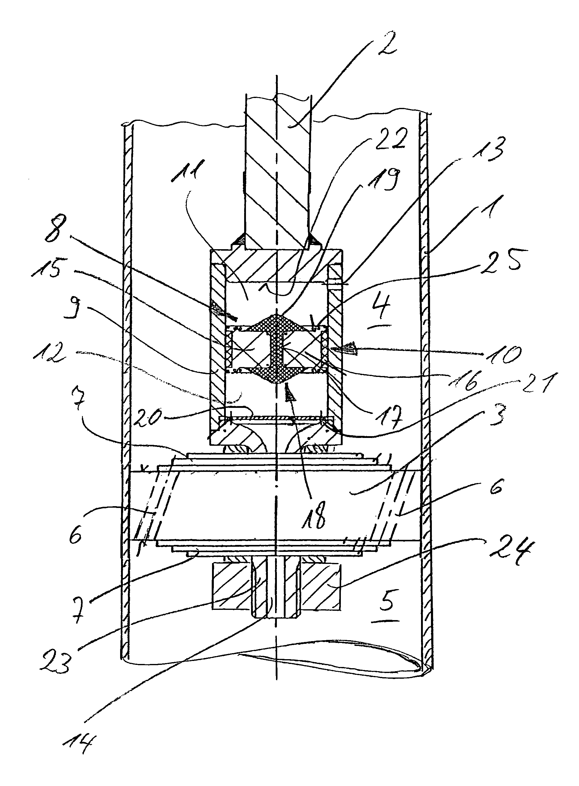
[0013]FIG. 1 is a section through the vicinity of the working piston in a dashpot with, in the present case, a solid-walled cylinder. Cylinder 1 is closed at the top and bottom and charged with shock absorption fluid. Working piston 3 travels up and down inside cylinder 1 on one end of a piston rod 2. The working piston 3 in the illustrated example is indirectly connected, and partitions cylinder 1 into two compression-decompression compartments 4 and 5. Piston rod 2 travels into and out of cylinder 1 through a sealed port at the bottom. The fluid can flow out of one compression-decompression compartment and into the other through sloping bores 6. The ends of sloping bores 6 are capped top and bottom by resilient stacks 7 of cupsprings, each stack 7 accordingly decelerating the flow.
[0014]Cylinder 1 and piston rod 2 are attached by unillustrated means to the vehicle's wheel at one end and to its chassis at the other.
[0015]When vibrations of narrow amplitude occur between piston rod ...
PUM
Abstract
A dashpot featuring amplitude-dependent shock absorption, especially intended for the wheel of a vehicle and including a hydraulically parallel cylindrical pressure-compensation chamber (8). The pressure-compensation chamber is partitioned by an axially displaceable floating piston (10). At least one face (25) of the floating piston is provided with a resilient bumper (18).The object is a dashpot with a floating piston that arrives more gently at its limit inside the pressure-compensation chamber (8).The bumper is accordingly accommodated in an axial hollow (17) that extends through the body (15) of the floating piston.
Description
BACKGROUND OF THE INVENTION[0001]The present invention concerns a dashpot, or shock absorber, featuring amplitude-dependent shock absorption and including a hydraulically parallel cylindrical pressure-compensation.[0002]Dashpots with amplitude-dependent shock absorption have been developed for use with motor vehicle wheels in particular, to ensure that the level of shock absorption will decrease when the oscillations are both high in frequency and narrow in amplitude. A dashpot of this genus is known from EP 1 152 155 A1. The device features a hydraulically parallel cylindrical pressure-compensation chamber partitioned into two halves by an axially displaceable floating piston. At least one face of the floating piston is provided with a resilient bumper. The bumper is in the form of an O ring that fits into a groove. This is a drawback in that the bumper's performance curve is so hard that the floating piston's impact against the bottom of the pressure-compensation chamber will lead...
Claims
Application Information
Patent Timeline
Application Date:The date an application was filed.
Publication Date:The date a patent or application was officially published.
First Publication Date:The earliest publication date of a patent with the same application number.
Issue Date:Publication date of the patent grant document.
PCT Entry Date:The Entry date of PCT National Phase.
Estimated Expiry Date:The statutory expiry date of a patent right according to the Patent Law, and it is the longest term of protection that the patent right can achieve without the termination of the patent right due to other reasons(Term extension factor has been taken into account ).
Invalid Date:Actual expiry date is based on effective date or publication date of legal transaction data of invalid patent.

