Shielding for electrical cable assemblies

a technology of shielding and electrical cables, applied in the direction of electrical apparatus, shape memory alloy connection, coupling device connection, etc., can solve the problems of high speed communication generating radiated emissions capable of disrupting the performance of electrical assemblies, failure of electrical components,

Active Publication Date: 2007-08-14
HAMILTON SUNDSTRAND CORP
View PDF26 Cites 48 Cited by
  • Summary
  • Abstract
  • Description
  • Claims
  • Application Information

AI Technical Summary

Problems solved by technology

This type of high speed communication can generate radiated emissions capable of disrupting the performance of electrical assemblies both internal and external to an electrical unit associated with the cable assembly.
Breaking the shield creates an opening that permits emission outages that may cause a failure in the electrical component.

Method used


Image

  • Shielding for electrical cable assemblies
  • Shielding for electrical cable assemblies

Examples


Embodiment Construction

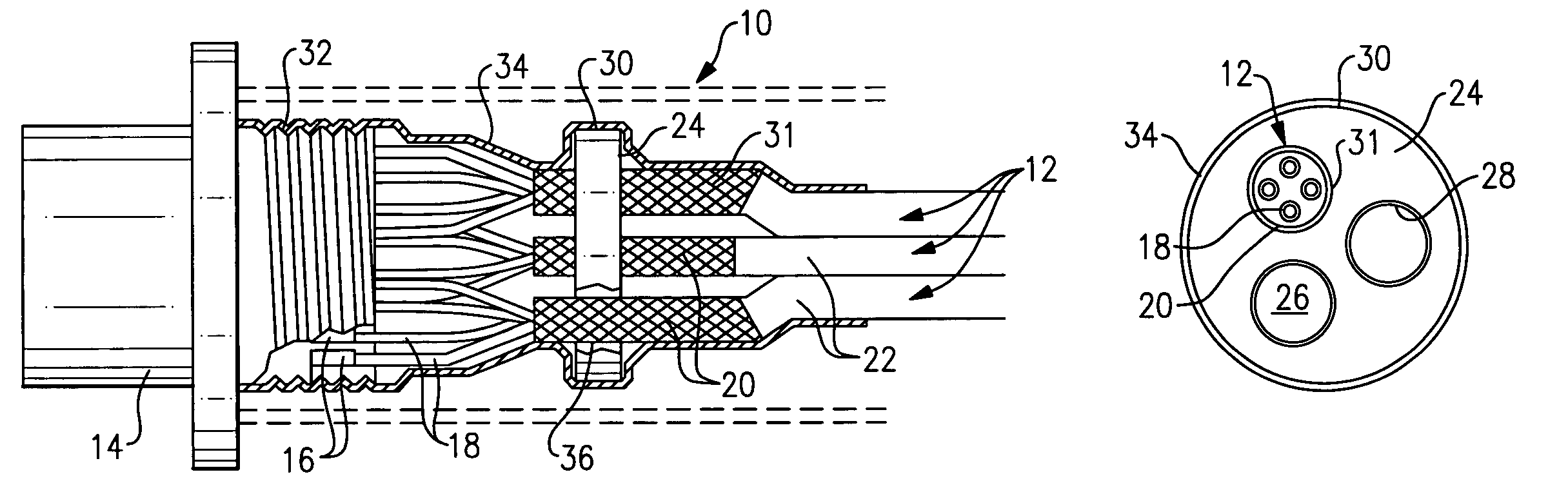
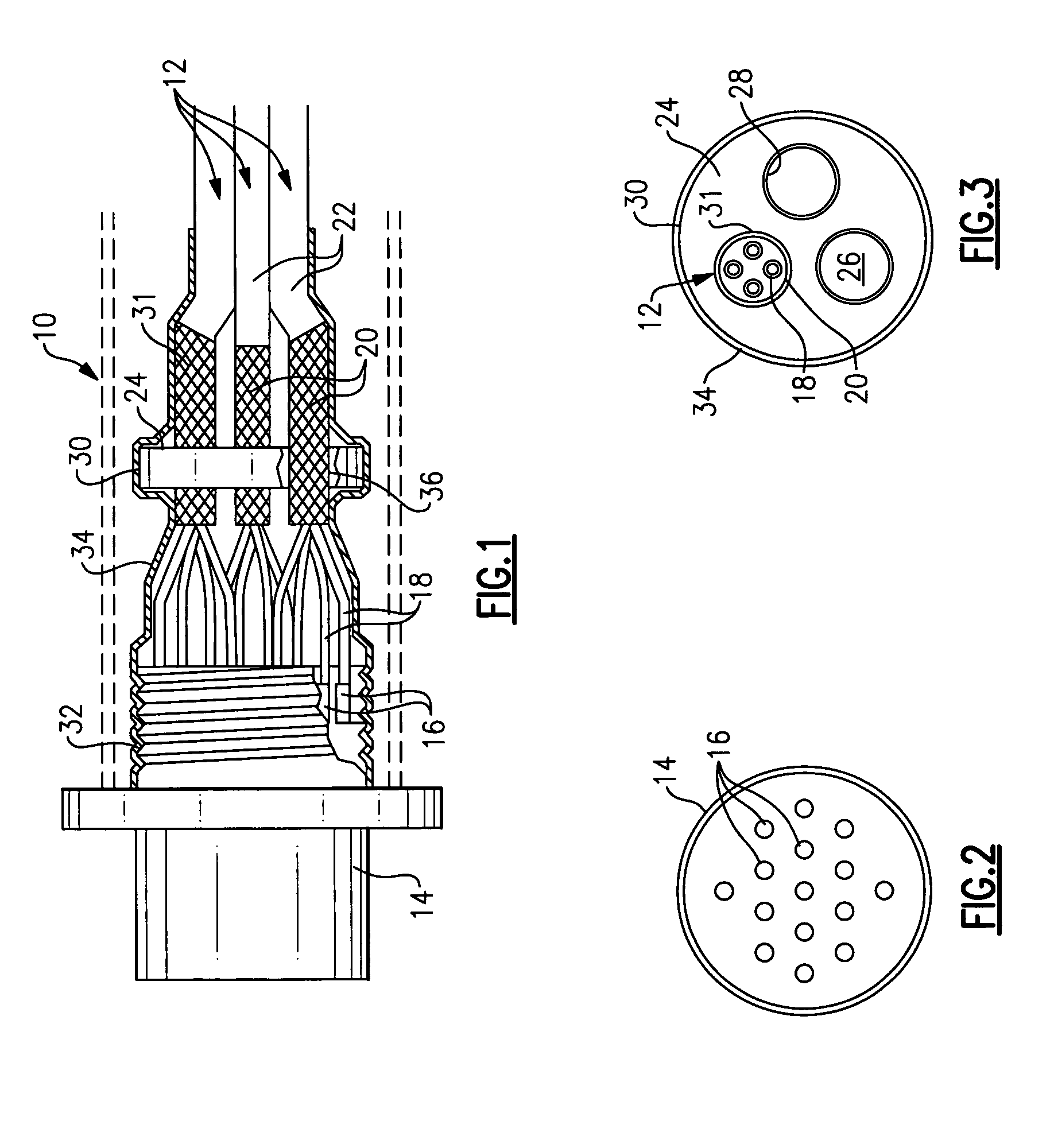
[0008]FIG. 1 schematically illustrates one example cable assembly 10. The cable assembly 10 includes multiple cables 12. In the example shown, a three port arrangement is provided for a 1394b connector. A common connector 14 is provided for the cables 12 and receives pins 16 that are electrically connected to another connector of an electrical component (not shown). Each cable 12 includes multiple wires 18 each having a pin 16 arranged at its end. An example pin configuration is shown in FIG. 2. The ends of the wires 18 are stripped and the pins 16 are crimped to the ends, as is known. A metallic shield 20, such as a braided shield, surrounds each set of wires 18 for each cable 12, as is known in the art. An external jacket 22 typically surrounds each shield 20 to insulate the shield 20 from the surrounding environment.

[0009]A conductive shield ring 24 is used to prevent any openings that would permit emissions from the rear of the connector 14 as is typical with a multiple cable ar...


PUM


Abstract

An electrical cable assembly is provided including multiple cables having wires. The cables each include a shield. A connector receives ends of the wires and includes an outer surface. A conductive shield ring has an outer periphery and includes multiple holes receiving the cables. The shield of each cable engages an inner surface provided by a corresponding hole in the shield ring. In one example, the circumference of each shield is soldered to the corresponding hole. A wrap engages the outer periphery and the outer surface to electrically connect the connector to the shields. In one example, the wrap is conductive heat shrink wrap that surrounds and engages the entire outer surface of the shield ring.

Description

BACKGROUND OF THE INVENTION[0001]This invention relates to an apparatus and method for shielding a cable assembly having multiple cables connected to a common connector.[0002]A 1394b data communication bus is capable of transmitting 400 Mbits / sec over copper wire. This type of high speed communication can generate radiated emissions capable of disrupting the performance of electrical assemblies both internal and external to an electrical unit associated with the cable assembly. In one example, the communication signals are carried over multiple ports, for example three ports. Each port is connected to the electrical unit's external connector through a shielded cable. The three cables must meet at the same external connector, which use crimp style pins in one example. The attachment of each port's cable causes a break in the cable shield to allow the wires to enter the rear of the connector. Breaking the shield creates an opening that permits emission outages that may cause a failure...

Claims


Application Information

Patent Timeline
Patent Type & Authority Patents(United States)
IPC IPC(8): H01R9/03
CPCH01R4/01H01R9/032H01R4/02H01R13/6588H01R13/65912
Inventor DRIESSEN, DARIN R.DOLFI, EUGENE W.SENO, MICHAEL A.CANCIAMILLE, JACK S.
Owner HAMILTON SUNDSTRAND CORP
Why Eureka
Try Eureka