
Vehicle seat with vibration monitoring ability

a vehicle seat and vibration monitoring technology, applied in the field of system and method for measuring vibration, can solve the problems of inability to use in actual working conditions, inability to tap a disc to a piece of equipment such as a vehicle seat, and inability to monitor whole body vibration in a working environment. , to achieve the effect of eliminating operator discomfort and ensuring a safe environment for accelerometer

Inactive Publication Date: 2007-08-14
SEARS MFG
View PDF11 Cites 28 Cited by
  • Summary
  • Abstract
  • Description
  • Claims
  • Application Information

AI Technical Summary

Benefits of technology

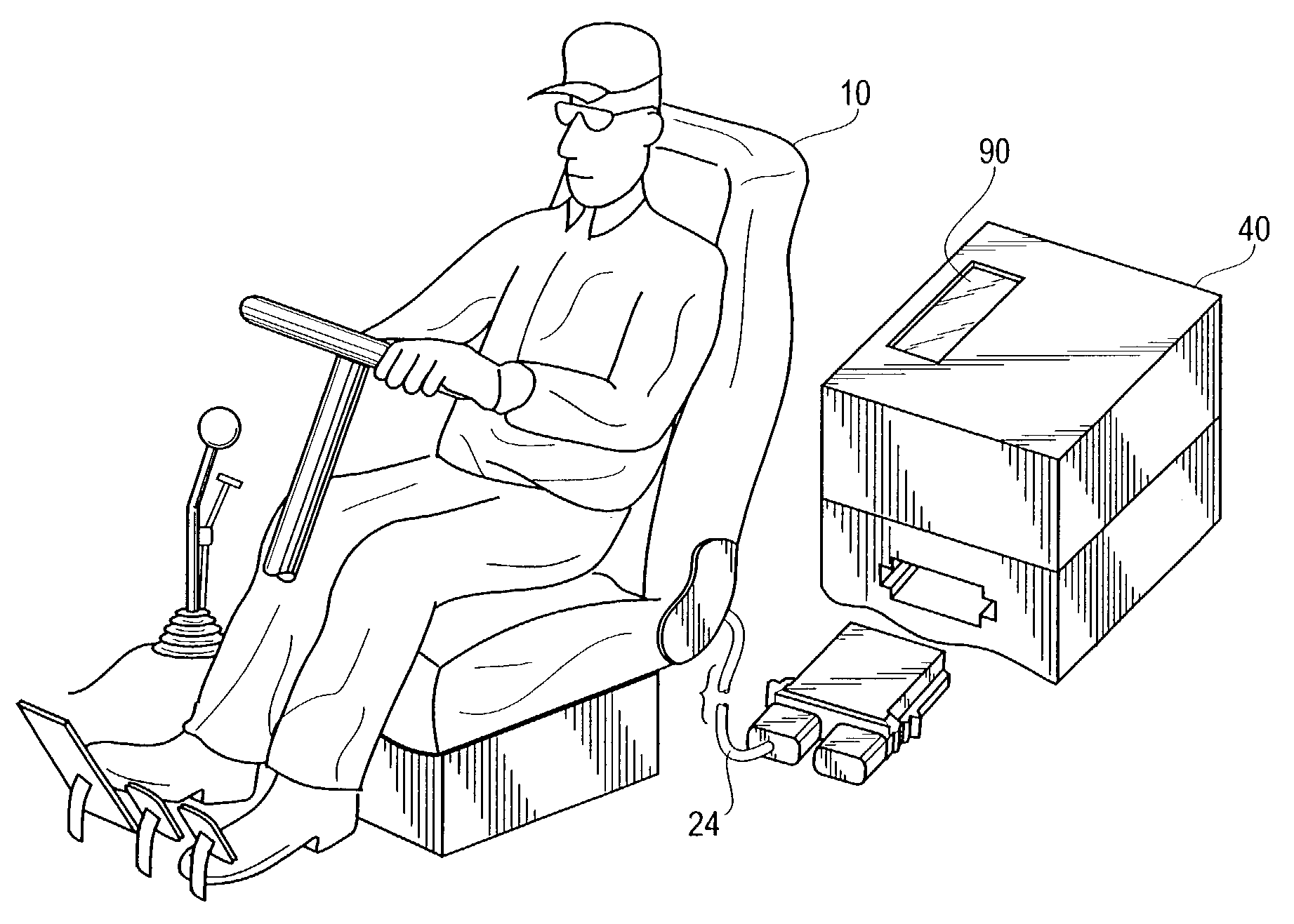
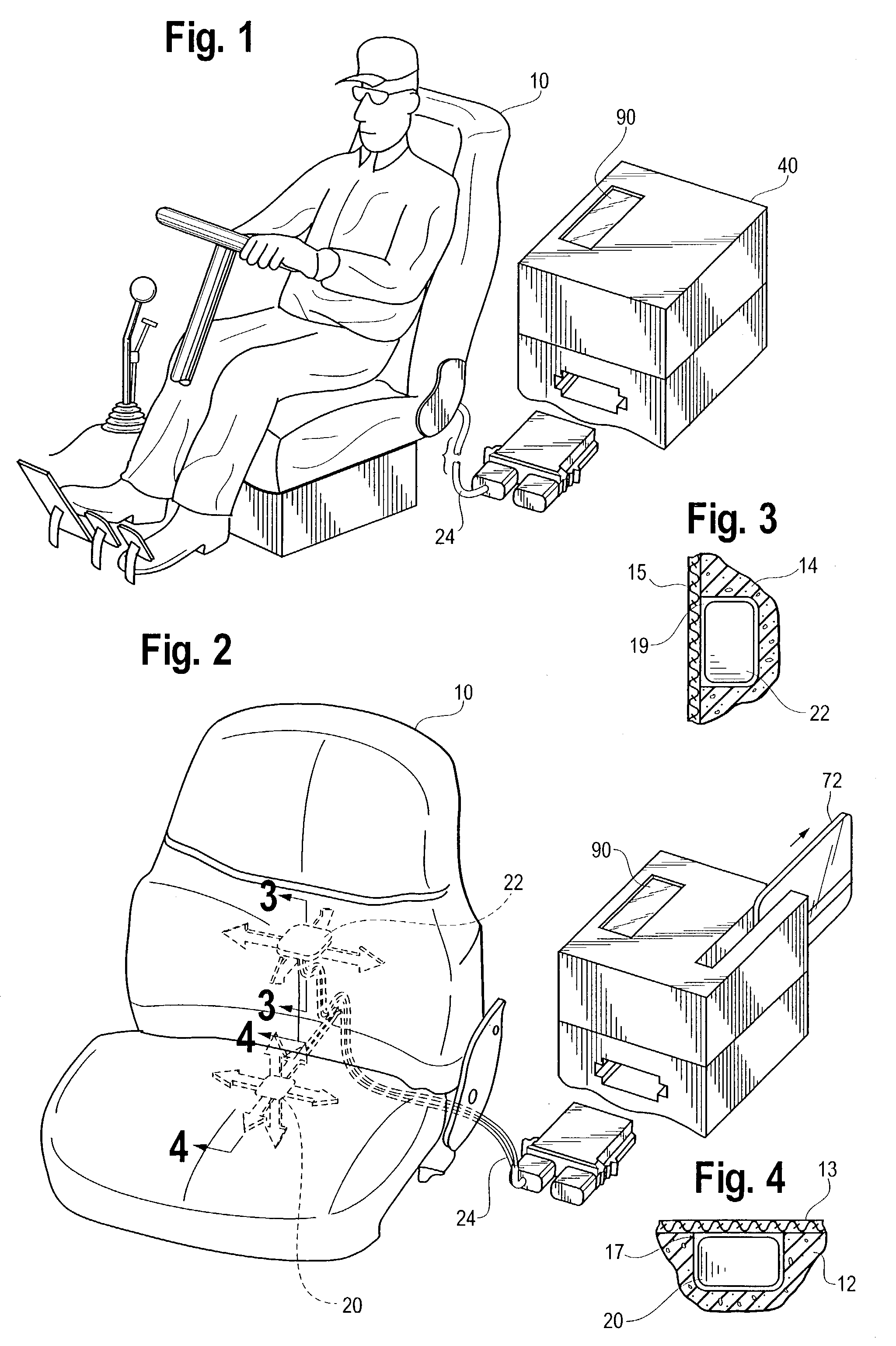
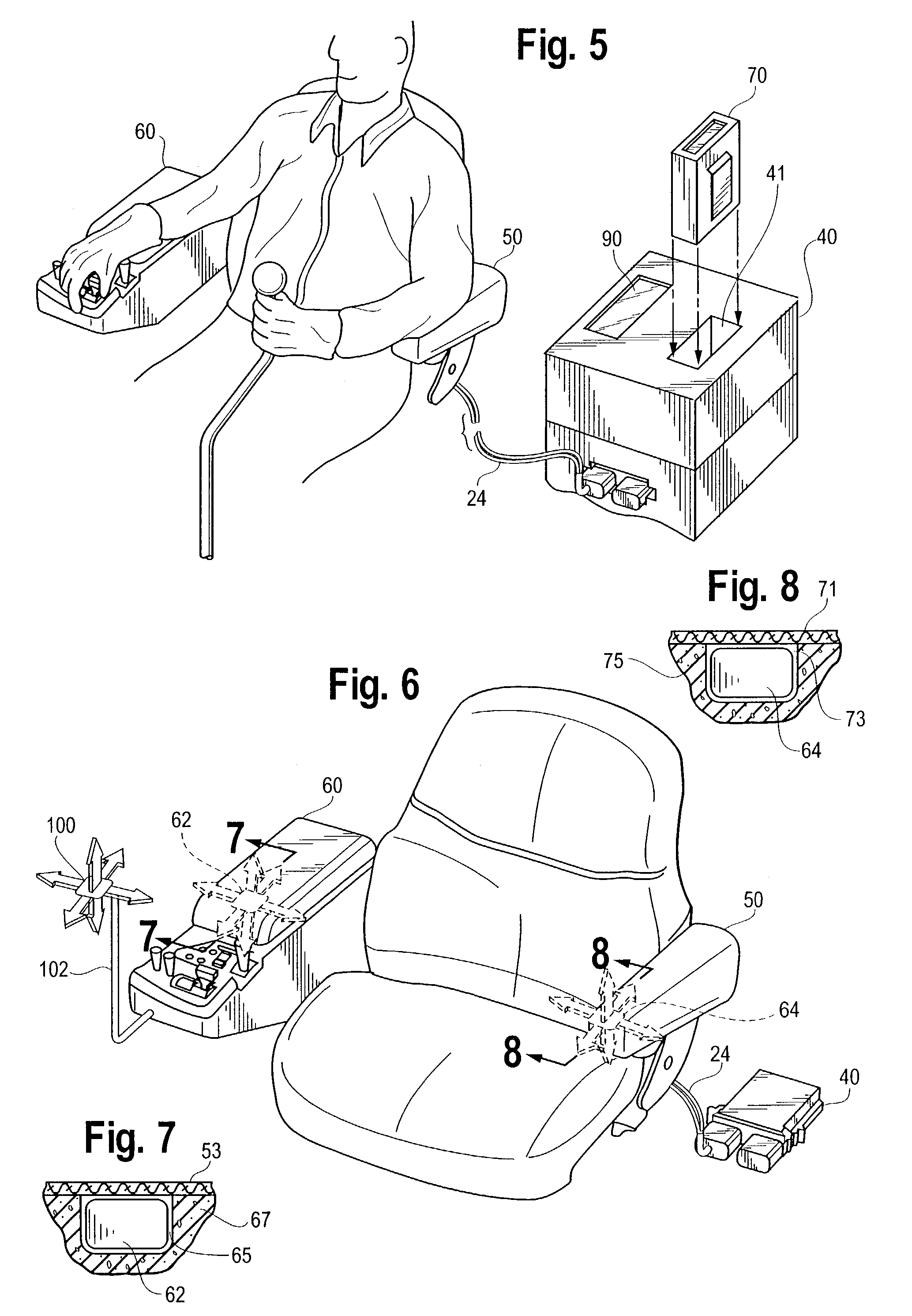
[0006]The present invention overcomes the above mentioned problems associated with the laboratory device by providing on a piece of moving equipment, such as a vehicle seat, at least one motion measuring device that may be located under the seat cover and / or backrest cover. In another embodiment, the motion measuring device may be housed within the cushions to measure the motion component experienced by the seat occupant. Locating the motion measuring device in a location beneath the outer surface of the equipment eliminates operator discomfort and provides a secure and safe environment for the accelerometer.

Problems solved by technology

The problem, however, is that there are no known systems for monitoring whole body vibration in a working environment.
This laboratory design, however, suffers from several drawbacks that make it impractical for use in actual working conditions.
First, taping a disc to a piece equipment such as a vehicle seat is not practical.
Through normal usage it would almost be inevitable that the disc would fall off of the equipment or be damaged during use by being exposed to the working environment.
Moreover, in a vehicle seat application, the disc, with its raised section would be uncomfortable for an operator to sit upon, and this would no doubt lead to the accelerometers being routinely removed.
In addition, the laboratory set-up does not provide a way to measure vibration at other locations such as at the arms of an operator.
Nor would having discs taped to the equipment present an aesthetically pleasing appearance.
Once an accelerometer had either been removed, tampered with, fallen off, or simply have been damaged by virtue of being left exposed to the working environment, the ability to measure and record body vibration would be lost.

Method used


Image

  • Vehicle seat with vibration monitoring ability
  • Vehicle seat with vibration monitoring ability
  • Vehicle seat with vibration monitoring ability

Examples


Embodiment Construction

[0018]Set forth below is a description of what are currently believed to be the preferred embodiments or best examples of the invention claimed. Future and present alternatives and modifications to the preferred embodiments are contemplated. Any alternates or modifications in which insubstantial changes in function, in purpose, in structure or in result are intended to be covered by the claims of this patent.

[0019]As shown in FIGS. 1 and 2, in one embodiment, the present invention may be used with a seat 10, which includes motion measuring devices such as accelerometers 20 and 22. The motion measuring device may be designed to measure motion such a vibration and / or acceleration in various directions such as the x, y and z axes. While two accelerometers are shown in the preferred embodiment, with accelerometer 20 having the ability to measure acceleration or motion in the x, y, and z axes, and accelerometer 22 having the ability to measure acceleration or motion in the x and y axes o...


PUM


Abstract

The present invention concerns a system for measuring the vibration an operator of a piece of the equipment encounters while operating the equipment. The system includes at least one motion measuring means, such as an accelerometer. The accelerometer may be affixed to the equipment or integrated into the equipment. In addition, motion data recording equipment that is in electrical communication with the accelerometer may also be provided. An alarm may be used to indicate that a preset limit has been or is about to be exceeded.

Description

BACKGROUND OF THE INVENTION[0001]The present invention relates to a system and method for measuring vibration. More specifically, the present invention concerns a vehicle seat which has built into the seat and other seat components such as armrests and control consoles accelerometers or transducers which are coupled to a processor for recording and processing data relating to the vibrations encountered by the occupant of the seat.SUMMARY OF THE INVENTION[0002]An increasing concern in the workplace is the amount of vibration an operator encounters while operating various pieces of moving equipment such as motorized vehicles and construction equipment such as, for example, a jackhammer and the like. Currently, standards exist in the European Union which state that an operator should not be exposed to conditions exceeding 1.15 m / s2 for whole body vibration during an eight hour period. Monitoring and insuring that an operator's exposure does not exceed prescribed limits is the responsib...

Claims


Application Information

Patent Timeline
Patent Type & Authority Patents(United States)
IPC IPC(8): B60Q1/00B60N2/02B60N2/50
CPCB60N2/0244B60N2/50B60N2002/0272B60N2/0272B60N2210/50
Inventor KOUTSKY, L. JOHNBRODERSEN, COLE T.TUMAN, WILLIAM
Owner SEARS MFG
Learn More