Lamp masking method and apparatus

a masking method and masking technology, applied in the field of vehicle lamps, can solve the problems of spot blindness and much more intense output, and achieve the effects of reducing heat buildup, reducing heat buildup, and speeding up heat accumulation

Inactive Publication Date: 2005-07-05
ILLUME
View PDF27 Cites 50 Cited by
  • Summary
  • Abstract
  • Description
  • Claims
  • Application Information

AI Technical Summary

Benefits of technology

[0009]When used as a headlamp, the exemplary embodiment of the invention gives a motorist direct control of intensity and zones of illumination. The motorist can adjust the illumination intensity and zone for specific traveling conditions, i.e. weather, terrain, time of day etc. This creates a safer environment to operate the motor vehicle.
[0010]Practice of the exemplary embodiment of the invention is achieved with one, high intensity light source supported by a headlamp assembly having a reflective region for directing light through the light transmissive portion of the assembly. This structure can provide high beam, low beam and fog lamp outputs from a headlamp without resort to multiple bulbs and bulb housings.
[0012]The material can be any material where when electrically energized alters the light emitted from the light source to the illumination zone. Preferably, the material is a PDLC material (polymer dispersed liquid crystal) which scatters light rather than absorbing the light to block its transmission. This characteristic greatly reduces heat build up associated with masking a halogen lamp, whose high intensity light output causes a rapid build up of heat in any material which absorbs that light. The material can be affixed to the enclosure in any suitable manner apparent to these of ordinary skill in the art in view of this disclosure. In the exemplary embodiment, the enclosure is coated with the material.

Problems solved by technology

Spot blindness was only a problem for halogen lights since these lights produce a much more intense output when compared with non-halogen lamps.

Method used


Image

  • Lamp masking method and apparatus
  • Lamp masking method and apparatus
  • Lamp masking method and apparatus

Examples


Embodiment Construction

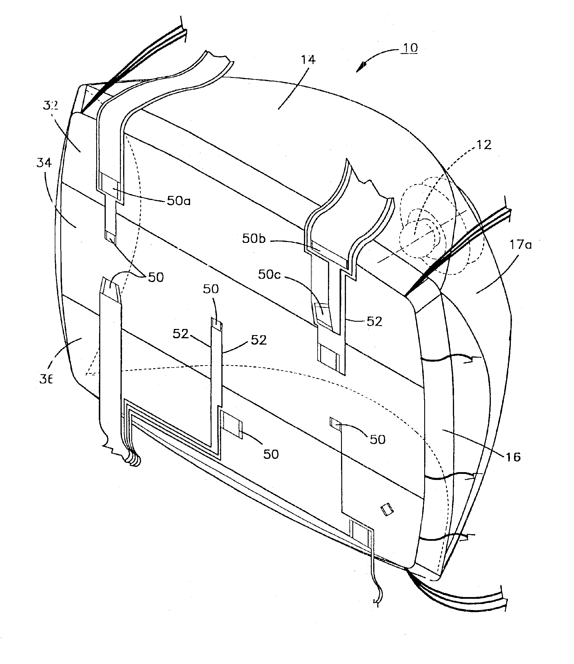
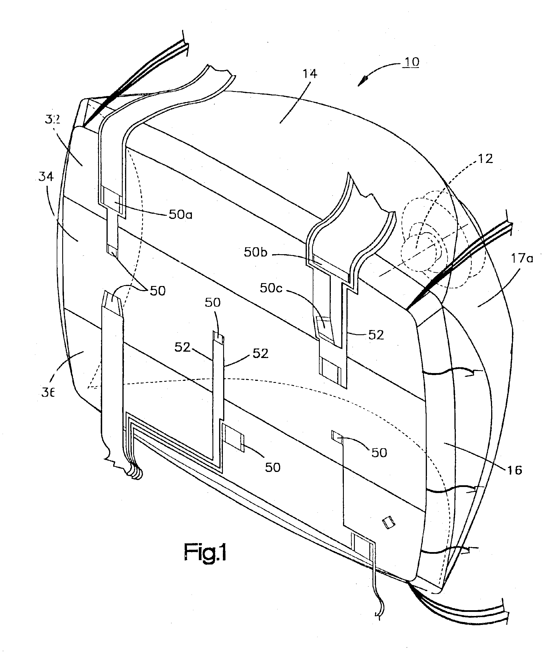
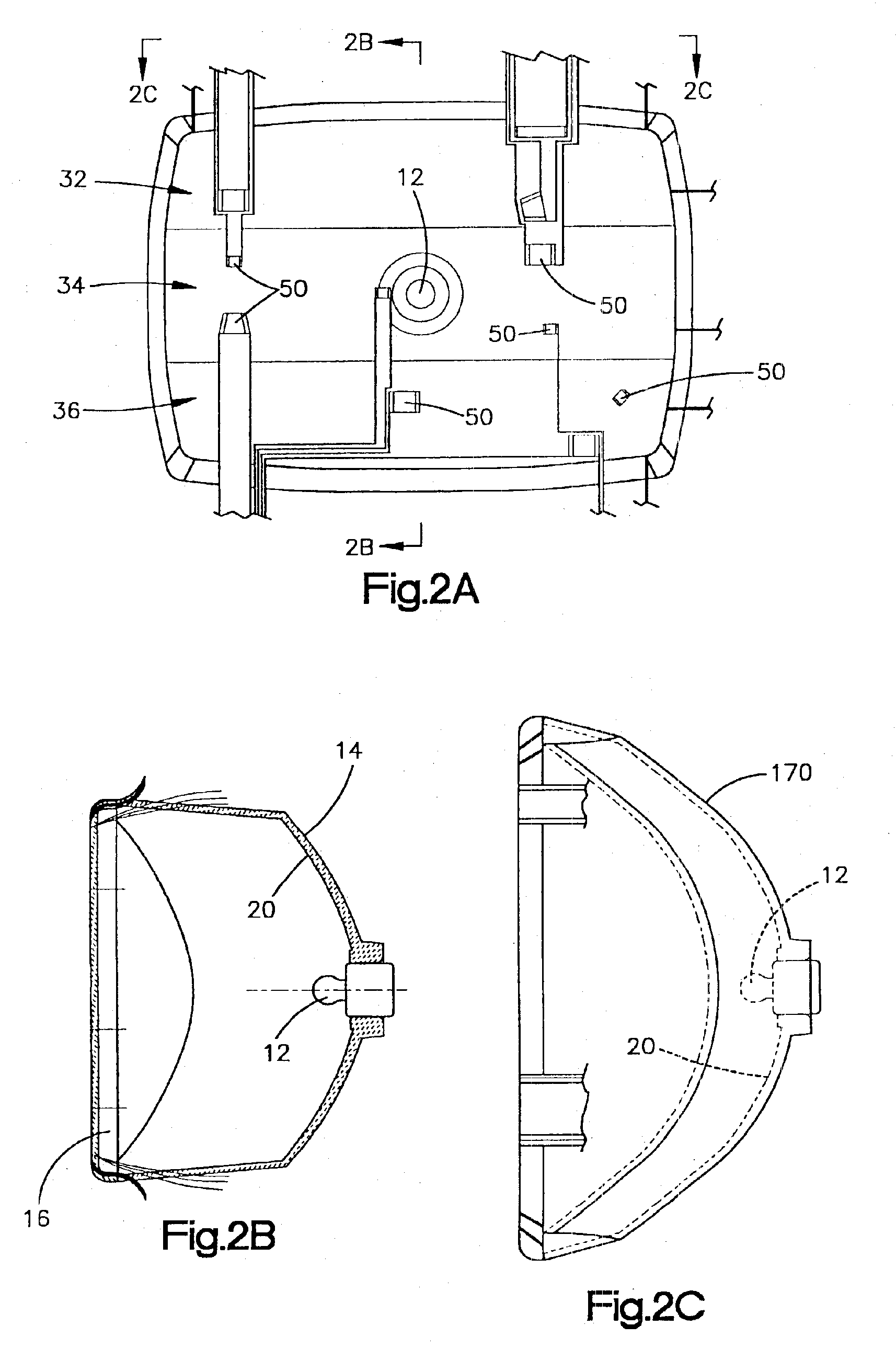
[0024]Turning now to the drawings, FIG. 1 illustrates a headlamp assembly 10 that includes a headlamp bulb 12 for emitting light mounted to a bulb housing 14 having a light transmissive portion or lens 16 for emitting light from the headlamp bulb 12 to an illumination zone in front of the headlamp assembly 10. An interior surface 20 of the light bulb housing 14 reflects light reaching the surface 20 back into the housing interior so that it will exit the housing through the light transmissive portion 16. The bulb 12 can take the form of a traditional head lamp bulb or can be constructed from other known light sources. Some of such light sources include, for example, High Intensity Discharge (HID), Halogen, Flouorescent, Incandescent, and High Intesity Light emitting diode / diodes.

[0025]The light transmissive portion of the housing is coated at specified regions with a coating material. When these regions are electrically energized the coating material is rendered more light transmiss...


PUM

PropertyMeasurementUnit
frequencyaaaaaaaaaa
distanceaaaaaaaaaa
light transmissionaaaaaaaaaa

Abstract

A motor vehicle lamp assembly having a light source for emitting light and a source enclosure having a light transmissive portion for transmitting light from the light source to an illumination zone. The enclosure is affixed with a material which covers a selected region of the light transmissive portion of the enclosure. The material is electrically energized to alter an amount of light transmitted from the light source to the illumination zone. A drive circuit electrically coupled to the material energizes the material to control a light output from the lamp assembly.

Description

CROSS REFERENCE TO RELATED APPLICATIONS[0001]The present application is a continuation in part containing common subject matter with U.S. patent application Ser. No. 10 / 108,827, filed Mar. 27, 2002, now U.S. Pat. No. 6,550,943 which is a continuation-in-part of U.S. patent application Ser. No. 09 / 967,437 which was filed in the United States Patent and Trademark Office on Sep. 28, 2001, now U.S. Pat. No. 6,558,026 which is a continuation in part of U.S. patent application Ser. No. 09 / 865,402 which was filed in the United States Patent and Trademark Office on May 25, 2001, now U.S. Pat. No. 6,491,416, and which is entitled “Headlamp Masking Method and Apparatus.” The subject matter of the co-pending application and issued U.S. Patent are hereby incorporated by reference.FIELD OF THE INVENTION[0002]The present invention concerns a vehicle lamp having a control for selectively rendering portions of the lamp light transmissive under vehicle operator control.BACKGROUND ART[0003]All motor ...

Claims


Application Information

Patent Timeline
Patent Type & Authority Patents(United States)
IPC IPC(8): B60Q1/00B60Q1/26F21V3/04F21V3/00G02F1/13G02F1/1334F21S8/10F21V14/00F21W101/10F21Y101/00
CPCB60Q1/00B60Q1/0041B60Q1/26F21S48/1731F21V3/04G02F2001/13347F21S41/645G02F1/13347
Inventor STRAZZANTI, MICHAEL
Owner ILLUME
Why Eureka
Try Eureka