Process and a plant for recycling carbon dioxide emissions from power plants into useful carbonated species

a technology of power plant and carbon dioxide, which is applied in the direction of machines/engines, magnesium compounds, hydrogen sulfides, etc., can solve the problems of reducing the required fuel to supply power, eliminating co2/sub>production completely, and reducing the emissions of co2 into the atmosphere. , to achieve the effect of increasing the energy efficiency of the plant and reducing the emissions of co2

Active Publication Date: 2009-10-06
SAIPEM SPA
View PDF17 Cites 53 Cited by
  • Summary
  • Abstract
  • Description
  • Claims
  • Application Information

AI Technical Summary

Benefits of technology

[0014]More particularly, in accordance with the present invention, the above object is achieved with a process for recycling carbon dioxide emissions from a fossil-fuel power plant into useful carbonated species, which process primarily comprises the steps of: a) combustion of a fossil fuel, thereby generating heat and a hot exhaust gas containing CO2; and b) converting the heat into energy. The process is characterized in that it further comprises the steps of: c) cooling the exhaust gas; and d) biologically transforming at least a portion of the CO2 contained in the cooled exhaust gas into carbonated species, thereby obtaining a low CO2 exhaust gas and producing useful carbonated species. The low CO2 exhaust gas obtained in step d) can be released in the atmosphere without increasing the problem of greenhouse effect.
[0019]This invention thus proposes the integration of a CO2 transformation process into a fossil-fuel power plant in order to produce bicarbonate species which are useful by-products, and thereby reducing at the same time the CO2 emissions. This CO2 transformation process is based on a biological reactor which enables CO2 transformation into bicarbonate in an aqueous environment. The CO2 is then precipitated into a stable solid product, safe for the environment. As can be appreciated, in the present invention, only water, a biocatalyst and a cation source are required for carbon dioxide sequestration.
[0041]The coupling of the biological process for CO2 removal and transformation to a fossil-fuel power plant leads to a reduction of CO2 emissions into the atmosphere and an increase energy efficiency of the plant. Furthermore, the required cooling of the flue gas enabling proper operation of the bioreactor is coupled with energy recovery systems that produce additional power output for the power plant.

Problems solved by technology

However to date, CO2 emissions from fossil-fuel power plants are generally not contained or reduced.
It is known that such an increase in greenhouse gases causes climate changes which could lead to various environmental problems, such as an increase in violent weather events, significant temperature warming in specific areas, changes in the precipitation pattern trends and a rise of ocean level.
This approach reduces the required fuel to supply power, but does not eliminate CO2 production completely.
However, as yet, the environmental impact of this technology has not been demonstrated (U.S. Pat. No. 6,475,460).
However, this method only constitutes a temporary storage, since in the medium term, the displacements of the earth crust are capable of bringing about a release of CO2.
Moreover, although there are hundreds of depleted sites around the world, their total capacity is after all limited, and there is an obligation to land case the geological formations involved.
However, CO2 chemical transformation into bicarbonate fertilizer requires methane, hydrogen and nitrogen.
However, methane and hydrogen are required.
Other carbonates cannot be obtained.
Although some solutions have been proposed in the past for reducing CO2 emissions in general, few of them have shown to be efficient or commercially viable for different reasons.
Moreover, a very few, if not none, of the solutions proposed specifically apply to CO2 emissions from fossil-fuel power plants.

Method used


Image

  • Process and a plant for recycling carbon dioxide emissions from power plants into useful carbonated species
  • Process and a plant for recycling carbon dioxide emissions from power plants into useful carbonated species
  • Process and a plant for recycling carbon dioxide emissions from power plants into useful carbonated species

Examples


Embodiment Construction

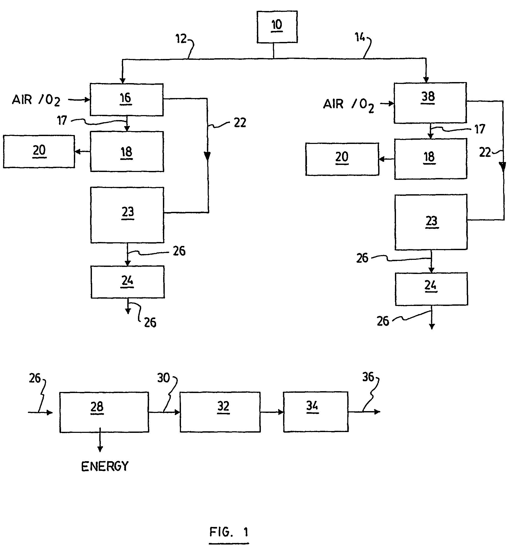
[0044]FIG. 1 shows a flow sheet where a biological process is integrated to energy generation processes.

[0045]In this diagram, the nature of the fossil fuel (10), either coal (12) or natural gas (14), used to power the plant leads to two different branches.

[0046]In the case of coal (12), the fuel is burned in a combustion chamber (16); the heat (17) is used to produce steam from water in a heat recovery steam generator system (18). The steam propels turbines and alternators (20) producing electric power. The flue gas (22) exiting the combustion chamber (16) is treated to remove ash, NOx and / or SO2 (23). In the current configuration of power plants, the gas is finally exhausted by a stack (24).

[0047]In the context of this invention, the gas (26) is not exhausted at this stage, but rather sent to additional heat exchangers and energy recovery systems (28) to cool it down to an adequate temperature for the biological process. Energy is produced by this step. The cooled gas (30) is then...


PUM

PropertyMeasurementUnit
depthsaaaaaaaaaa
pHaaaaaaaaaa
temperatureaaaaaaaaaa

Abstract

A process is disclosed for recycling carbon dioxide emissions from a fossil-fuel power plant into useful carbonated species The process primarily comprises the steps of: a) burning the fossil fuel, thereby generating heat and a hot exhaust gas containing CO2; and b) converting the heat into energy. The process is characterized in that it further comprises the steps of: c) cooling the exhaust gas; and d) biologically transforming the CO2 contained in the cooled exhaust gas into carbonated species, thereby obtaining a low CO2 exhaust gas and producing useful carbonated species. The low CO2 exhaust gas obtained in step d) can be released in the atmosphere without increasing the problem of greenhouse effect.

Description

CROSS REFERENCE TO RELATED APPLICATIONS[0001]This application is the U.S. National Stage of International Application PCT / CA2003 / 001496 filed Sep. 29, 2003, and published in English on Apr. 8, 2004 under International Publication Number WO 2004 / 028667 A1, and applicant claims priority from Canadian Patent Application Number 2,405,635 filed Sep. 27, 2002.FIELD OF THE INVENTION[0002]The present invention relates generally to processes and apparatuses used for energy production in fossil-fuel power plants. More particularly, it concerns a process and a plant for the sequestration of carbon dioxide emissions emanating from fossil-fuel power plants, and for the production of useful carbonated species.BACKGROUND OF THE INVENTION[0003]Fossil-fuel power plants produce the main part of the energy actually consumed worldwide. Energy is generated from the combustion of fossil-fuels such as coal, natural gas and fuel oil. The use of biomass to fuel the power plant is also within the scope of th...

Claims


Application Information

Patent Timeline
Patent Type & Authority Patents(United States)
IPC IPC(8): F02C1/00B01D53/62F23J15/02C10L1/02B01D53/84
CPCB01D53/84Y02C10/02B01D2257/504Y02A50/20Y02C20/40Y02E20/32
Inventor FRADETTE, SYLVIERUEL, JEAN
Owner SAIPEM SPA
Why Eureka
Try Eureka