Supercharge Your Innovation With Domain-Expert AI Agents!

Thermal printer having heat radiation plate

a technology of heat radiation plate and printer, which is applied in the direction of printing, power drive mechanisms, instruments, etc., can solve the problems of increasing cost and deteriorating the quality of images printed on recording paper, and achieves excellent quality, reduced cost, and high image quality.

Inactive Publication Date: 2007-08-14
ALPS ALPINE CO LTD
View PDF7 Cites 2 Cited by
  • Summary
  • Abstract
  • Description
  • Claims
  • Application Information

AI Technical Summary

Benefits of technology

The present invention provides a thermal printer that can print high-quality images quickly and at a reduced cost. The printer includes a rotatable platen roller, an elongated thermal head, and a head supporting member with an elongated head supporting portion. A heat radiation plate is arranged between the thermal head and the head supporting portion to escape heat generated during printing. The thermal head can be adjusted to closely match the heat radiation plate, ensuring quick cooling of the thermal head. The printer can print excellent quality images quickly and at a high rate of speed. The heat radiation plate is composed of a head fixing portion and a heat radiation portion, and the head fixing portion has slit grooves to securely curve the printer head and prevent ink ribbon wrinkling. The adjusting member is composed of screw members, making it easy to adjust the thermal head curve. The head supporting member has arm portions capable of supporting both ends, ensuring reliable pressure-contact with the platen roller.

Problems solved by technology

Because of this, heat generated from the thermal head 53 during printing can not easily escape through the head supporting portion 55b which also serves as a heat radiation plate, resulting in the thermal head 53 heating up during the printing process, thus possibly deteriorating the quality of an image printed on a recording paper.
Furthermore, the thickness of the head supporting portion 55b made of materials like aluminum must be thick because the thermal head 53 is bent by tightening the adjusting screw 58, which increases the cost.

Method used


Image

  • Thermal printer having heat radiation plate
  • Thermal printer having heat radiation plate
  • Thermal printer having heat radiation plate

Examples


Embodiment Construction

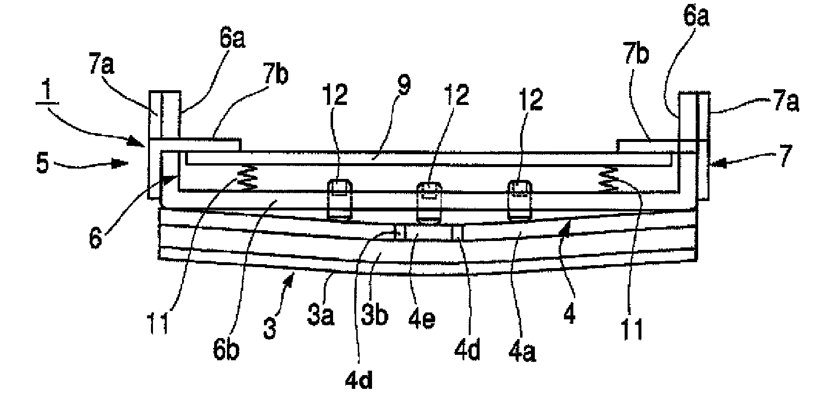
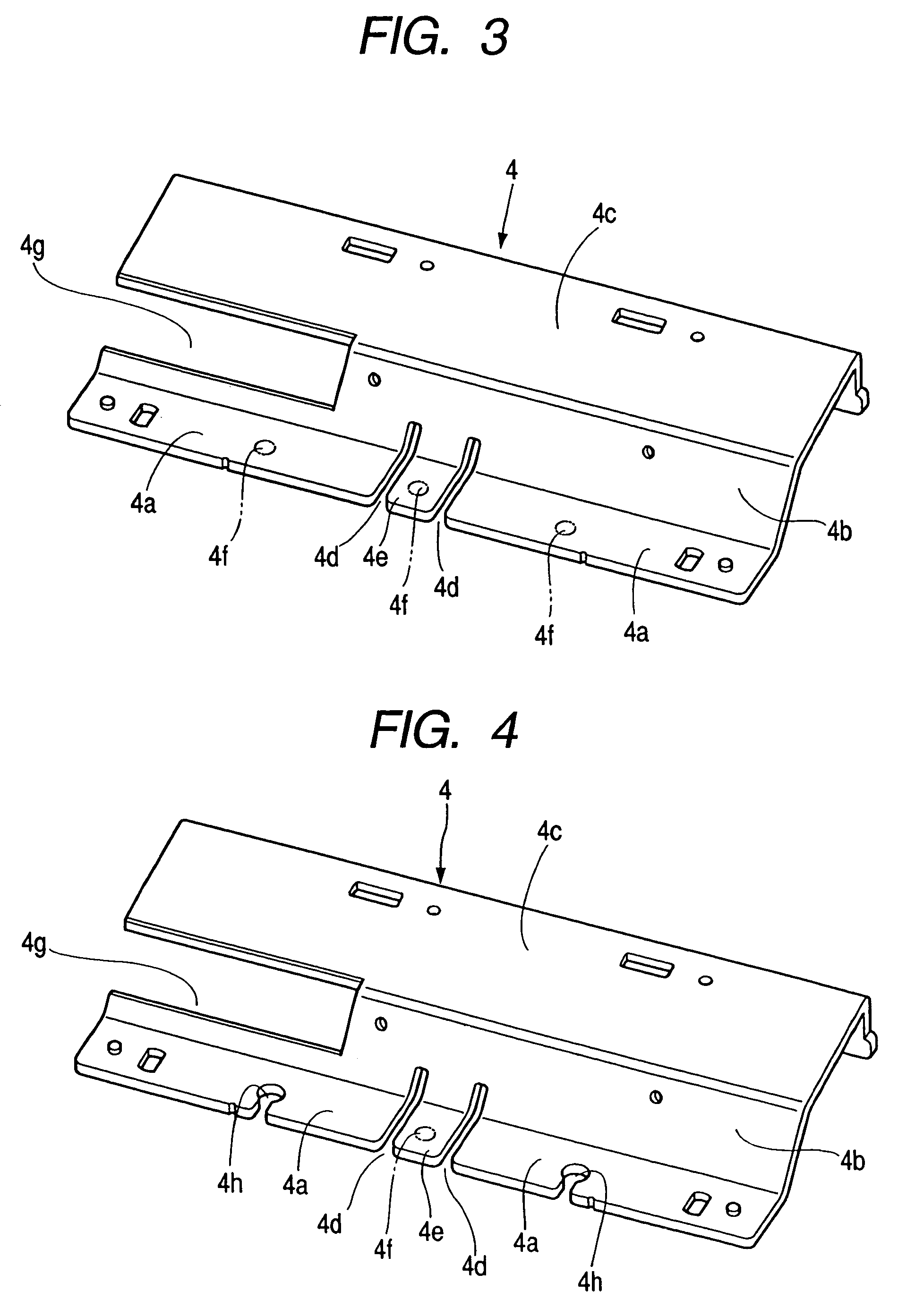
[0033]Hereinafter, a preferred embodiment of a thermal printer of the present invention will now be described with reference to the accompanying drawings. FIG. 1 is a perspective view showing a printing part 1 of a thermal printer, FIG. 2 is a diagrammatic plan view of FIG. 1, FIG. 3 is a perspective view showing a heat radiation plate, and FIG. 4 is a perspective view showing a modification of a heat radiation plate according to the present invention.

[0034]First, the thermal printer of the present invention will be described with reference to FIGS. 1 to 3. An elongated cylindrical platen roller 2 is rotatably supported on the frame side (not shown).

[0035]Also, above the platen roller 2, an elongated cylindrical thermal head 3 composed of line heads being movable toward or away from (head up / down) the platen roller 2 is arranged.

[0036]As shown in FIG. 2, the thermal head 3 includes a head substrate 3a which has a plurality of heating elements (not shown) arranged in a row at the bot...


PUM


Abstract

A thermal printer includes a rotatable platen roller; an elongated thermal head which is movable toward or away from the platen roller; and a head supporting member having an elongated head supporting portion for supporting the thermal head formed at an end. A heat radiation plate through which heat generated from the thermal head during printing can escape is arranged between the thermal head and the head supporting portion, and the thermal head can be adjustably curved toward the platen roller via the heat radiation plate by an adjusting member arranged in the head supporting portion.

Description

[0001]This application claims the benefit of priority to Japanese Patent Application Nos. 2004-092384 filed on Mar. 26, 2004 and 2004-186783 filed on Jun. 24, 2004, both herein incorporated by reference.BACKGROUND OF THE INVENTION[0002]1. Field of the Invention[0003]The present invention relates to a thermal printer which is suitable for performing printing on a recording paper by selectively generating heat from a plurality of heating elements of a thermal head based on print information.[0004]2. Description of the Related Art[0005]A conventional thermal printer 51 will now be described with reference to FIGS. 5 and 6, a cylindrical platen roller 52 is rotatably supported on a frame side which is not shown. Also, above the platen roller 52, a rectangular thermal head 53 composed of line heads capable of moving toward or away from (head up / down) the platen roller 52 is arranged.[0006]The thermal head 53 is composed of a head substrate 53a which has a plurality of heating elements (n...

Claims


Application Information

Patent Timeline
Patent Type & Authority Patents(United States)
IPC IPC(8): B41J25/312B41J2/335B41J2/32B41J2/325B41J2/375
CPCB41J2/325B41J2/335B41J2/3358B41J2/375
Inventor GOTO, TAKASHIINOUE, YASUTOSHI
Owner ALPS ALPINE CO LTD
Features
  • R&D
  • Intellectual Property
  • Life Sciences
  • Materials
  • Tech Scout
  • Unparalleled Data Quality
  • Higher Quality Content
  • 60% Fewer Hallucinations
Learn More